1. NTRODUCTION
According to [1] and [2], in the context of a globalized market, industrial systems must constantly change to achieve new requirements of accuracy, security, flexibility and speed in order to remain competitive. In this context, the automation is presented as a solution to ensure efficient and effective productivity, while providing opportunities to adapt it to new requirements.
The development of automation projects can be approached in different ways depending on the person/team and system’s complexity. Thus, a common approach is the direct implementation, where a person uses his skill and experience to develop the solution, as shown in the project examples in [3]–[6]. Similarly, other approach for automation requires to define a methodology to formalize a system evaluation using formal tools [7]–[9]. These present various advantages over direct implementation, for instance, this approach allows to embrace complex problems systematically; thus facilitates the validation, verification and implementation of future changes in a project. In addition, approaches based on formal tools facilitate interdisciplinary teamwork. Despite the amount of articles presenting the use of formal methods in automation projects, it is found a lack of end-to-end approaches resulting in solutions that are no scalable to different applications.
Moreover, since 1970, the PLCs (Programmable Logic Controller) have been tools that have driven industrial automation. Due to the wide use of these control devices, the software and hardware elements have been standardized internationally, such as standards IEC 1131 and IEC 1499 [10], [11]. Due factors such as: the increasing complexity of control problems, the demand for high quality solutions and the need to reuse software, among others [7]. Consequently, it is recommended to program PLCs supported on specifications taken from the use of methods. In this context, a widely used tool in different applications for verification and validation of discrete event systems are the Petri nets [12], [13]. Considering the importance of integrate both structured methodologies based on formal methods and the programing of PLCs, for a successful develop of automation projects, this article focus in develop a procedure not only for the implementation of the automation software but approaching since the problem definition to the system validation, to accomplish this, a structured process is presented, where the tools to define user requirements, acceptance criteria and system requirements were established. From which, the functional states and the activities’ refinement of the automation process were identified through a Top/Down approach. Then, a formalization the processes dynamics was performed, using formal modeling tools, such as Petri nets. Additionally, these models were verified through simulation based on predefined scenarios. Finally, the verified and validated models were mapped using Ladder programing language according to standard IEC 61131. This approach could be applied in different automation systems. In particular, this work presents the use of this procedure to design and implementation of an automation system for a Plastic Bag Making Machine (PBMM), obtaining a satisfactory acceptance from users. This evidence the benefits of a structured approach considering the integration of modeling tools in the different stages of an automation project, requirements, design and implementation, in accordance with the demands and restrictions of the current automatic systems.
This article is structured as follows: section two describes materials and methods according to the context of the automation project. Then, the results and discussions are presented in relation to the implementation, test plan and identification of faults and validation of the application. Finally, conclusions are presented.
2. MATERIALS AND METHODS
Figure 1 shows the first part of the proposed procedure. Which starting from needs declaration, the stakeholders are defined, then, the internal and external restrictions are specified until obtain the operational system limits. Parallel, the stakeholder’s expectations should be specified in order to define the operational scenarios. Finally, both operational limits and scenarios are used to define the acceptance criterial. In the next sub-sections each process of Figure 1 is detailed.
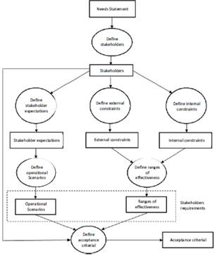
Figure 1 Specification process diagram for
stakeholder’s requirements.
2.1. Stakeholder requirements definition
New market trends encourage the reduction of the development cycle and implementation time of new technologies. For that, it is necessary to establish requirements that allow to develop the "right product" for everyone involved, which is a vital part of the development process of the project. To identify the requirements of a project it is important to have control over the activities and manage the development of an appropriate and cost-effective solution [14]–[17].
An automation project begins with a statement of needs by a manufacturer. For the case of the Plastic Bag Making Machine (PBMM), a document with a lists of elements, input and output variables, action descriptions for each element of the process and a sequence of operation of the machine was presented. From these basic requirements established by the stakeholders, the design specifications and PBMM's elements were determined [14]–[17]. In Figure 1 shows the procedure for the formal definition of the stakeholder’s requirements.
a) Stakeholders definition
A stakeholder can be any person or organization that has an opinion, a responsibility or can be influenced or affected by the proposed system [14]. To identify the stakeholders, it was necessary to analyze the life cycle of some PBMMs on the market and identify the people who interact with them. Thus, it was identified three stages with their respective Stakeholders.
· Manufacturing: provide the main functional information of the machine (designer and investor).
· Operation: provide information about the interface and machine operation, according to its usability and process variables (operator and supervisor).
· Maintenance: provide functional requirements presented in the machine operation and its interface (operator).
To identify the stakeholder expectations for the system, interviews, lecture of descriptive documentation and state of the art analyses were made. A detailed information about the operation expected in the machine to be automated, and additional requirements were obtained.
b) Functional requirements
Functional requirements are the characteristics that the system must implement in order to accomplish its objective in a successful way. To determinate this requirements, it is necessary to define all the necessary steps and procedures to transform the materials and energy inputs in the desired outputs. In the case of the PBMM, its input material is a roll of plastic (polyolefin, polypropylene, polyethylene), which provides a two-layer plastic film that is transformed into packet bags with lateral seal (desired output) as showed in Figure 2.
Figure 3 shows the general process of sealing bags, the stages of separation, extraction, sealing, cutting and unwinding are presented. The machine must allow both manual and automatic operation modes. Additionally, it is required to have a touch screen as the input and output interface for the system information.
In the sealing process there are two variables that dominate PBMM configuration: cycles per minute (CPM) and the bag length. The CPM is the number of times the sealing head is cycled up and down in a minute, that is, the number of sealed bags per minute. The bag length is measured between each cut made by the sealing head controlled by the displacement of the feed roller during each cycle. The product of these two variables corresponds to the length of the plastic bag that is unbent and turned into bags every minute. This variable is called linear velocity of the process (LVP).
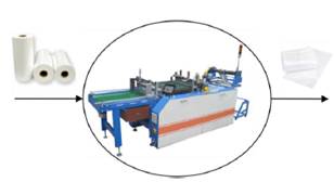
Figure 2 PBMM raw input material and output
product.
The control requirement of this process was to control the CPM, which depends on the speed of a gear motor and the type of plastic to seal, since it must ensure the welding time and the desired bag length avoiding waste of material.
Once the programmed bags are finished, the machine's seal stops and waits for all bags to be conveyed from the extractor to the conveyor belt, then the bag sealing restarts. The list below shows variables that must be controlled during manufacture bags.
· Bag length: Distance between seals, equivalent to the rollers’ feed in each cycle.
· • Cycles per minute: Number of sealed bags per minute; it is proportional to the main shaft speed.
· Temperature: Temperature in the sealing head to seal and cut the plastic.
· Extraction rate: bag extraction bands linear velocity in m/min, proportional to the electric motor speed.
· Unwinding speed: Linear speed in m/min of the surface of unwinding rollers, proportional to the speed of the electric motor.
· Band feed: Determines how much time the conveyor belt of the separation system is on.
· Output bag waiting: timeout before starting the separation process, so that bags on the extraction bands fall on the band.
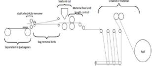
Figure 3 PBMM process.
c) Nonfunctional requirements
Non-functional requirements are the functionality and capacities that the Stakeholders requested to facilitate or improve the machine operation but that are not directly necessary for nominal operation of the machine, in the case of the PBMM, there are two nonfunctional requirements:
· Monitoring window: Provides feedback of process variables in real time such as head temperature, energy consumption, number of bags and number of packages.
· Recipes: Save different bag parameters, with a recipe it was not a necessary to configure each parameter of the process manually.
d) Internal and external constraints
The internal constraints are the restrictions or limits in production capacities due to technical specification of the used equipment and the physical restrictions in the material and energy transformation such as critical temperature or cutting speed.
The external constrains can be divide in two: 1) national and international normative that affect any process variables. 2) physical environmental conditions that affect the performance of the system.
In this point is important to evaluate whether detected constrains impede to accomplish the project objectives and requirements. In this case is necessary to discuss whit the client the possible change or retrofitting necessary to guaranty the desired performance.
For the PBMM, it was not found national or international norms with an effect on the project. The machine should be energized to 220V AC at 60 Hz. Internal constraints are given by the technology and equipment provide by the manufacturer.
· Sensors and input devices: Generally, these entries correspond to signals that users send to the system, measurements or environment variables. The machine has buttons that allow the manual activation of some actuators, and there are three buttons for emergency stops, stop process and start the machine. To control specific machine functions, for instance, temperature was required thermocouples. The user could enter discrete signals (binary variables) and numerical parameters (Word type variables) through the touch screen.
· Actuators and output devices: Output elements are those that enable the transformation of a roll of plastic bags into packages, some of them are: motors, main shaft, extracting and separation bands, servomotors and resistances which provide the increase in temperature in the sealing head. To select a specific output element, the manufacturer provided catalogs and manuals.
· Control elements: A PLC was the center of the main automation process. An E-CDT LM3108 PLC was used, it had its own programming software PowerPro Version 2.1.2 B, which uses the international standard IEC 61131-3 including six programming languages (LD, FBD, IL, ST, SFC and CFC.). For the motor speed control, the manufacturer used inverters Danfoss VLT Micro Drive FC 51. All inverters had the same operating characteristics and programming. To control the servomotor position and speed was used a servodrive SDB20NK.
· Human machine interface (HMI): a touch screen MT8104iH was used to control, monitoring and configurate the machine functions. A software name EasyBuilder8000 V4.65.02 (EB8000) was used to program the HMI.
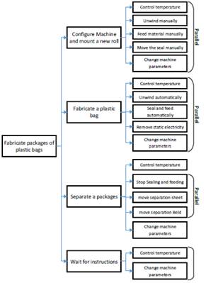
Figure 4 Operation scenarios, (a) from the manufacturer's point of view
e) Operating scenarios
The operating scenarios are a structuring mechanism for discussion of capacity requirements. These has a hierarchically organization based on time and are used as a method to integrate the users in the design process [18], [19]. For the case of the PBMM, Figure 4 shows the operation stages described from operator’s point of view. A high-level operating scenario is defined considering used case diagrams, then, each operating scenario is proposed in its constitutive low-level application scenarios describing if the applications scenarios are executing sequentially of parallel
f) Effectiveness range
The effectiveness ranges are the limit values for the critical operational variables, this ranges are calculated based on the internal and external restrictions [20].
As an example, the max LVP is a critical operational variable which is limited to 40 m/min because the bag extraction speed is calculated in 42.5 m/min according to the max motor speed. The range of effectiveness of other operational variables of the PBMM are presented in Table 1
Table 1 Effectiveness ranges for some operational PBMM variable.
|
Effectiveness range |
Value |
|
Unwinding speed |
104.8 m/min. |
|
Bag extraction speed |
42.5 m/min |
|
Cycles per minute (CPM) |
160. |
|
Feeding rate |
40 m/min. |
|
Sealing head temperature |
260ºC |
g) Acceptance Criteria
Once the operation scenarios, restrictions and ranges of effectiveness were defined, the results were socialized and discussed with stakeholders to define outcomes (behavior and values) that will complement each requirement and create a check-list that facilitates the evaluation of the project when it is finally delivered. For the PBMM, some acceptance criteria were:
· When the machine starts, no function should be available until a button in the screen is enabled.
· After taking the number of programmed bags, the machine must stop, remove the package and restart the automatic seal.
· If the number of separated packages is equal to the number of scheduled packages, the process should stop and only manual functions should be enabled.
· While the machine is working automatically, the spindle must keep moving with the CPM scheduled on the screen.
· The sealing head temperature head should be varying between 30 and 260°C, and the programmed value should be maintained on the screen.
2.2. System Requirements
After defining the stakeholder’s requirements, the automation system requirements were defined using modeling tools such UML, IDEF0 and the definition of the functional states. The process for the definition of this requirements is shown in Figure 5. each stage of this process is detailed below.
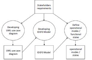
Figure 5 Requirement definition process.
a) Use case diagrams development
The use case diagram is a tool to determinate the system requirements from a user point of view. To develop the use case diagram, it was necessary to identify the system, actor and interactions between them [21].
As an example, the PBMM, its system is the machine by itself, the actors are the people who interact with the machine (operator, maintenance technician and the supervisor). Figure 6 shows a general use case diagram for the interaction between the PBMM and operator. In this diagram, three use cases are identified, which could be divided into more detailed use cases.
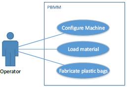
Figure 6 General use case diagram.
b) Developing IDEF0 model
An IDEF0 model describes the system behavior, the functions that compose the entire transformation of the system’s inputs into the desired outputs. An IDEF0 model is composed of a series of hierarchical diagrams whose main elements are the boxes which represent functions or processes and its dynamics are defined by the line segments that enter or exit according to the following convention [22]:
· Inputs: represents what is being transformed or consumed by the function to produce the function outputs. It is represented by an incoming arrow to the left side of the box.
· Controls: represents conditions that must be known before the function produces the desired output. It is represented by an incoming arrow on the upper side of the box.
· Outputs: represents what is produced by the function. It is represented by an arrow that appears on the right side of the box
· Mechanism: represents the tools and instruments used by the function. Represented by an incoming arrow on the bottom side of the box.
All this element is presented in Figure 7.
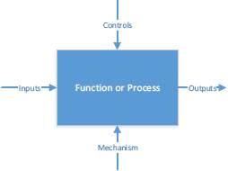
Figure 7 General IDEF0 model [22].
The procedure proposed in this article proposes that IDEF0 model should be developed from the use case diagram. The IDEF0 model of the PBMM is not presented due to space restrictions.
c) Definition of Functional states
A state in a dynamic system could be defined as the information necessary to describe the future trajectory of the system whit specific entries or action sequences, the functional states or operation modes try to generalize the concept of state to a higher level, it is about characterize the situation in which a process is based on its past, the functions it must perform and the possible transitions to new situations. To define these states, the following points must be taken into account:
· The operating modes are related to changes in functionality, which can be related to the use scenarios.
· Using the use case diagrams, functional states can be identified as high-level use cases, ie those that include or extend other use cases and generally from one use case to another produce global changes or in several elements to the time.
· A change of functional state or operation mode, occurs when an input produces a change in the dynamics of the subsystems and/or a state change in several elements.
· Functional states do not refer to naming the sub functions that make up the process, but to the overall functioning of the system.
· A system cannot be in two states at the same time, so there is no parallelism between them, but the sequence between states is not necessarily linear.
· A state can even be a null dynamic in all the elements.
This procedure is applied to the PBMM resulting in the next functional states:
· Lock: The machine does not perform any function, except the temperature control and parameterization of the machine.
· Stop: The machine only performs manual features.
· Sealing: The machine performs the bag sealing process automatically.
· Separating: The separation system only works if the rest of the machine is stopped.
Finally, this procedure should be repeated for each functional state, obtaining the functional sub-states that compose each high-level state until get the functional states in a field device level (sensors and actuators).
2.3. PBMM dynamics model for validation and implementation
From the functional states, a Petri Nets (PN) system functional model was developed following the steps detailed in [23]–[26]:
· A place for each functional status is assigned: naming from P0 to Pn, according to the number of states.
· Possible transitions between states were defined: for each possible change from one state to other, a transition is assigned and connected with the corresponding arcs.
· Shooting pre-conditions for each transition are added: A place is assigned to each transition with an input relationship of type test. Each location represents the conditions to change from one state to another.
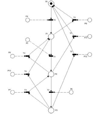
Figure 8 PN model of PBMM dynamics
According to the described procedure, the model of the dynamics between different functional states and sub-functions was developed, where places were allocated to each state and the possible transitions between states were defined. The general PN is shown in Figure 8 and locations are described in Table 2.
Table 2 Allocation of places in the PN
|
Place |
Description |
||
|
State |
P0 |
Locked |
|
|
P1 |
Stopped |
||
|
P2 |
Sealing |
||
|
P3 |
Separating |
||
|
Preconditions Shooting |
P4 |
Enable machine from button in the screen |
|
|
P5 |
Real Temp.≥ Programed Temp.( 50ºC) |
||
|
Start signal from a button or screen |
|||
|
P6 |
Number of programmed bags |
||
|
Sealing head is up |
|||
|
P7 |
Separation stage finished |
||
|
The packet count failed |
|||
|
P8 |
Stop signal from button or screen |
||
|
P9 |
Emergency stop from button |
||
|
P10 |
Stop signal from a button or screen or count packages finished. |
||
|
P11 |
Emergency Signal from stop button |
||
|
P12 |
Emergency Signal from st |
||
To verify the models was used HPsim software, it was simulating each operating scenarios, verifying blocking, reachability and conservativity, among others model properties [27]. The final models showed no blockages, reachability or conservativity problems.
One advantage of this approach evidenced during the modeling of the sub-function F8, bag separation, where the simulation allows the identification of a blockade that indicated the presence of a flaw in the real system.
To validate the models, it is necessary to determine if the models represented accurately the real system behavior, to this, simulations scenarios are defined in order to create a simulation steps that represents the conditions of the real system, then the sequence of states is compared with the desired system behavior. If the model does not successfully accomplish the correct representation of the system behavior, it must be debugging until get a validated model.
This last procedure should be applied to every functional state until obtain a petri net model of all the levels of the system dynamics.
3. RESULTS
3.1. Implementation
The automation of the system consists of several elements that must be interconnected in order to satisfy the system requirements by controlling the state of the actuators depending the system inputs. This accountability depends on the software in the PLC, this mean, the PLC programing is the final step in the implementation of the automation project. In this last step, petri nets model developed in the last section was used to generate the software control using a systematic procedure of mapping from petri nets to ladder diagram programing language.
d) Mapping rules from petri nets to ladder
· First step - programing trigger preconditions: A transition will be enabled to shoot when all the places with an input relation have at least one marking equal to the weight of the arc. Therefore, to bring this condition to the Ladder language, the transition is represented as a coil in each line of code, and the places with input relation are represented as serial contacts forming a logical AND, in this way only when all the contacts are activated the coil representing the transition will be activating. When any of the contacts is missing the transition is deactivated.
· Second step – Programing the change marking for each possible transition shot: The shoot of a transition consists in the elimination of a place marking with an input relation to the transition and the addition marking in a output place with relation. Places with test or inhibitor relation to the arc do not change the marking when the transition is trigged. To map this behavior to Ladder language, a contact corresponds to the triggered transition, it is set in each line of code, then the places with output relation are mapped as coils in reset condition and the pleases with input relation are mapped as coils in set condition, in this way, when the transition is activated a logical zero will be written (0) in the places with reset condition and a logical one (1) will be written in the places with set condition, these logical values will be maintained even after the transition is deactivated and will change only when another transition is triggered.
· Third step - Program sub-functions as functional blocks: The two previous procedures must be repeated to each sub-function and the resulting ladder program of each sub-function must be code into an independent functional blocks (Funtion Blocks) which will be declared later in the program.
· Fourth step - Programing of the equivalence of each place: The equivalence of each place of the petri net must be programmed so that when a place is activating, the actuators or sub-functions change their state corresponding states according to the functional state represented by the place. To accomplish this, if the place represents a functional state, the place is program as a contact and the actuators or functional blocks associated to it are programed as coils in the same line. If the place represents a sensor or process variable, the place is program as a coil, which, is activate by the contacts representing the corresponding sensors or variables.
The PBMM PLC control program is develop by applying this procedure with the petri nets model presented in section 2.3. Figure 9 shows an example of the precondition mapping process described above. Figure 10 shows the change in marking after transition shoot mapping from petri Nets to Ladder language.
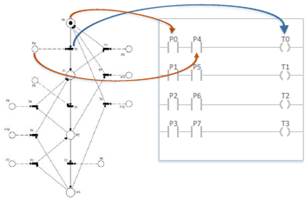
Figure 9 Preconditions mapping process from Petri Nets to Ladder language.
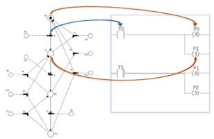
Figure 10 Change in marking after transition shoot mapping from petri Nets to Ladder language.
3.2. Program validation, verification and
Debugging
The process of verification and validation (V & V) determines whether the developed product for an activity could satisfy the requirements of that activity and user’s needs. This process can be achieved through analysis, evaluation, review, inspection and system testing [28].
In the case of automated systems, validation provide evidence that the implemented solution achieved the requirements assigned to software and hardware during the execution of each cycle of the system’s activities, providing correct solutions to the problem and user’s needs.
Facilitate the validation and verification was one of the main motivations for using formal models for the development of the automation project, thus it allowed to compare the system behavior with model simulations, identifying functional failures and making corrections based on the models without returning to the informal requirements. This reduced the project runtime and facilitated the maintenance of the control program’s structure and logic when changes were introduced.
4. DISCUSSION
4.1. Plan testing and failure identification
To confirm that the system works properly, the system process was implemented and proved in the machine. Knowing that the control program was based on a PN logic and that they describe the system behavior under a formal support which has already been verified, the real systems could be executed in parallel with the PN model to identify whether the system had irregularities in its dynamic.
To identify possible flaws in the system dynamics, the behavior was checked from the dynamics between functional states, to the dynamics of each sub-function [29]:
· Identify failure dynamics between states: If an incorrect status occurs or the process crashes during the execution, the programming has to be revised and corrected. Pre-conditions of the transition between two states, in which the error occurred, has to be changed and run again.
· Identify flaws in the dynamics of each state: If after applying the conditions for changing the state of the system, the system dynamic is not as expected for the active state, the relevant programming that corresponds to the meaning of the PN place that represent that state has to be reviewed and check whether the programming corresponds to the table of states and functions.
· Identify flaws in the dynamics of a sub-function: If within a state, the dynamics of a sub-function does not correspond to the desired one, the two steps above should be applied to identify and correct flaws in the programming of the subfunction.
4.2. System validation
To validate the automation system, the machine was presented in operation to the stakeholders, its behavior and properties were evaluated based on the acceptance criteria.
From the machine operating tests with different bag length configurations and CPMs, each of the defined acceptance criteria were checked. During testing, it was found that the behavior of the machine satisfies the requirements, but two flaws were found while feeding and counting bags, which are explained below:
· When the machine passes from separating packages to restart the sealing process, the head presses the free end of the plastic that is on the silicone roller, causing damage to each first bag package.
· One bag less is always sealed in each programed package.
To identify the cause of these failures, the model’s PN and functional states were reviewed, checking the meaning of place P6 corresponding to the preconditions to Sealing (P2) and separating (P3) where it was confirmed that the preconditions were defined according to the requirements. Therefore, their control algorithm was checked. It was found that the programming was correct so the Ladder code was displayed through an online simulation using PowerPro. This approach allowed to observe that in its first cycle, a bag was counted and fed, but this bag was cut only until the second cycle, therefore missing a bag in each package.
To solve this failure, it was necessary for the cutting and sealing activities to be included during the first cycle. To implement this solution, the feed bag was added during the separation activity and thus modifying the operating scenarios. After correcting these failures, the operation of the machine was tested again with stakeholders and the acceptance criteria was checked.
5. CONCLUSIONS
The article shows the development of a structured approach for automation projects and its implementation in a horizontal Plastic Bags Making Machine (PBMM), which was delivered in full operation. This procedure can be applied to different machines and processes allowing to systematically develop a web-based software implemented using PLC. This proposal allows implementing improvements and changes in the automation system to respond to market changes.
One weaknesses of some methodologies studied in literature is presented at the moment of defining the requirements causing difficulties in later stages, in response to this, this article addresses the definition requirements using different formal modeling tools that allow traceability to be carried out, connecting the needs of stakeholdes with the development of the final solution.
The project demonstrated the advantages of defining a structured procedure before approaching an automation project. Although the solution or the fulfillment of requirements is given by the implementation of the software and hardware control, the quality of this solution depends on how it was reached. This automation project showed characteristics such as easy maintenance, reusability, reliability, and modularity based on formal models of the dynamics process developed with PN. Additionally, specification requirements with standardized components models and graphical components facilitate the validation of requirements before approaching a solution.
Evaluating the performance of the machine in operation, it is concluded that the automation of the PBMM has productivity advantages over other electromechanical machines or manual machines, since it can operate at 160 CPM with a maximum production capacity of 40m/min, while manual production cannot reach more than 30 CPM or electromechanical machines (without servo-motors) more than 70 CPM. Comparing the performance of the machine with other automated machines with electronic control and programming, it is determined that the productive capacity of the machine equals or better the capacity of national sealing machines and in terms of user interface and possibilities of parameterization, monitoring and machine recipes, this machine exhibits an advantage to any other machine.
Based on the foregoing, the authors emphasize the importance of this kind of structured approach in the current automation projects in relation to social and business risks derived from a weak response to the needs of stakeholders considering the strict restrictions, for instance, time response and budget.
6. ACKNOWLEDGMENTS
To the School of mechanical engineering of the Universidad del Valle for the financial support, to the Maplas Cali manager, Guido Alfonzo Sanchez, for his collaboration.
7. ReferencEs
[1] D. H. Autor, “Why Are There Still So Many Jobs? The History and Future of Workplace Automation,” J. Econ. Perspect., vol. 29, no. 3, pp. 3–30, 2015.
[2] D. T. Matt, E. Rauch, and P. Dallasega, “Trends towards distributed manufacturing systems and modern forms for their design,” Procedia CIRP, vol. 33, pp. 185–190, 2015.
[3] M. Rihar and G. Godena, “Automation of specification process for PLC control systems\nsoftware,” 1999 7th IEEE Int. Conf. Emerg. Technol. Fact. Autom. Proc. ETFA ’99 (Cat. No.99TH8467), vol. 2, pp. 1289–1294, 1999.
[4] M. Liukkonen, “RFID technology in manufacturing and supply chain,” Int. J. Comput. Integr. Manuf., vol. 28, no. 8, pp. 861–880, 2015.
[5] M. Hincapié, M. de Jesús Ramírez, A. Valenzuela, and J. A. Valdez, “Mixing real and virtual components in automated manufacturing systems using PLM tools,” Int. J. Interact. Des. Manuf., vol. 8, no. 3, pp. 209–230, 2014.
[6] R. Bayindir and Y. Cetinceviz, “A water pumping control system with a programmable logic controller (PLC) and industrial wireless modules for industrial plants-An experimental setup,” ISA Trans., vol. 50, no. 2, pp. 321–328, 2011.
[7] G. Frey, “Automatic implementation of Petri net based control algorithms on PLC,” American Control Conference, 2000. Proceedings of the 2000, vol. 4. pp. 2819–2823 vol.4, 2000.
[8] J. Luo, Q. Zhang, X. Chen, and M. Zhou, “Modeling and Race Detection of Ladder Diagrams via Ordinary Petri Nets,” pp. 1–11, 2017.
[9] M. Markiewicz and L. Gniewek, “A Program Model of Fuzzy Interpreted Petri Net to Control Discrete Event Systems,” Appl. Sci., vol. 7, no. 4, p. 422, 2017.
[10] L. Bryan and E. Bryan, “Chapter 10 The IEC 1131 Standard and Programming Language,” in Programmable Controllers Theory Andimplementation, 2nd ed., Industrial Text Company, 1988.
[11] P. Bonfatti, D. Monari, and U. Sampieri, IEC 1131-3 programming methodology. Software engineering methods for industrial automated systems. 1997.
[12] T. Murata, “Petri nets: Properties, analysis and applications,” Proc. IEEE, vol. 77, no. 4, pp. 541–580, Apr. 1989.
[13] R. David and H. Alla, “Bases of Petri Nets,” in Discrete, Continuous, and Hybrid Petri Nets SE - 1, Springer Berlin Heidelberg, 2010, pp. 1–20.
[14] J. Dick, E. Hull, and K. Jackson, Requirements engineering. Springer, 2017.
[15] J. Dick, E. Hull, and K. Jackson, “Requirements Engineering in the Problem Domain,” in Requirements Engineering, Springer, 2017, pp. 113–134.
[16] W. Chapman, Engineering modeling and design. Routledge, 2018.
[17] L. E. G. Martins and T. Gorschek, “Requirements Engineering for Safety-Critical Systems: Overview and Challenges,” IEEE Softw., vol. 34, no. 4, pp. 49–57, 2017.
[18] J. S. Anderson and B. Durney, “Using scenarios in deficiency-driven requirements engineering,” [1993] Proc. IEEE Int. Symp. Requir. Eng., pp. 134–141, 1992.
[19] A. Arrieta, G. Sagardui, L. Etxeberria, and J. Zander, “Automatic generation of test system instances for configurable cyber-physical systems,” Softw. Qual. J., vol. 25, no. 3, pp. 1041–1083, 2017.
[20] P. H. Foo and G. W. Ng, “High-level Information Fusion : An Overview,” J. Adv. Inf. Fusion, vol. 8, no. June, pp. 5–28, 2013.
[21] “Use Case Diagram - UML 2 Diagrams - UML Modeling Tool.” [Online]. Available: http://www.visual-paradigm.com/VPGallery/diagrams/UseCase.html#actor. [Accessed: 14-Jul-2014].
[22] U. D. E. C. Station, “IDEF Family of Methods A Structured Approach to Enterprise Modeling & Analysis,” Idef0 Method report, 2010. [Online]. Available: http://www.idef.com/. [Accessed: 20-Mar-2014].
[23] A. A. V. Maobe, “System failure and perceived quality of services: a case of equity bank,” 2014.
[24] R. Sammi, I. Rubab, and M. A. Qureshi, “Formal specification languages for real-time systems,” Proc. 2010 Int. Symp. Inf. Technol. - Syst. Dev. Appl. Knowl. Soc. ITSim’10, vol. 3, pp. 1642–1647, 2010.
[25] G. Frey, “PLC Programming for Hybrid Systems via Signal Interpreted Petri Nets,” Proc. 4th Int. Conf. Autom. Mix. Process. ADPM, pp. 189–194, 2000.
[26] M. Ahmed, “A Comparative Analysis of Formal languages Based upon Various Parameters,” vol. 3, no. February, pp. 434–438, 2016.
[27] S. Rösch, S. Ulewicz, J. Provost, and B. Vogel-Heuser, “Review of Model-Based Testing Approaches in Production Automation and Adjacent Domains-Current Challenges and Research Gaps,” J. Softw. Eng. Appl., vol. 8, no. 9, pp. 499–519, 2015.
[28] P. Godefroid, Tests and Proofs, vol. 6706. 2011.
[29] D. M. Uede and W. D. Miller, The engineering design of systems: models and methods. John Wiley & Sons, 2016.