ARTICLES
IMPLEMENTATION AND AUTOMATION OF A SEQUENCING BATCH REACTOR WITH A LOGO-OBA6 PROGRAMMABLE LOW-COST CONTROLLER
IMPLEMENTACIÓN Y AUTOMATIZACIÓN DE UN REACTOR SECUENCIADO POR LOTES CON CONTROLADOR PROGRAMABLE DE BAJO COSTO
Yudy Andrea Londoño1, Milena Muriel2, Nelson Londoño Ospina3, Gustavo Peñuela4
1 Sanitary Engineer, PhD(c) in environmental engineering. E-mail: yudyandrea@gamil.com. GDCON Group (Diagnosis and Control of Pollution Group) School of Engineering, University Research Center (SIU), University of Antioquia, Calle 70 No 52 -21, Medellin-Colombia.
2 Electromechanical Technologist, Electrical Engineering student. E-mail: nury.muriel@udea.edu.co. GIMEL Group (Research Group Efficient Management of Electricity), School of Engineering, University Research Center (SIU), University of Antioquia, Calle 70 No 52 -21, Medellin-Colombia.
3 PhD in Engineering, Professor University of Antioquia. E-mail: nelson.londono@udea.edu.co. GIMEL Group (Research Group Efficient Management of Electricity), School of Engineering, University Research Center (SIU), University of Antioquia, Calle 70 No 52 -21, Medellin-Colombia.
4 PhD in Environmental Chemistry, Professor University of Antioquia. E-mail: gustavo.penuela@udea.edu.co. GDCON Group (Diagnosis and Control of Pollution Group) School of Engineering, University Research Center (SIU), University of Antioquia, Calle 70 No 52 -21, Medellin-Colombia.
Recibido: 8 de octubre de 2014. Aceptado: 15 de diciembre de 2014.
Received: October 8th, 2014. Accepted: December 15th, 2014.
ABSTRACT
This paper summarizes the results obtained in the implementation and automation of a sequencing batch reactor (SBR). First, the operating principle and the justification of the use of this type of reactor, as well as its applications, are explained. Subsequently, the design of both hardware and software for the automatic operation of the reactors is described, emphasizing the features and limitations of this type of system. Additionally, a formal design technique (petri networks) is used to develop a program that allows versatile, reliable and user-friendly operation, although it requires special programming strategies. Finally, the analysis, results, and conclusions are presented.
Key words: Automation, PLC, Sequencing batch reactor (SBR), programming, removal of environmental pollutants, wastewater treatment.
RESUMEN
El artículo resume los resultados obtenidos en la implementación y automatización de un reactor secuenciado por lotes (SBR). Inicialmente, se explica el principio de funcionamiento, se justifica la utilización de este tipo de reactores y sus aplicaciones. Posteriormente, se describe el diseño tanto de hardware como de software para la operación automática del reactor, haciendo énfasis en las características y limitaciones de este tipo de sistema. Además, utilizando una técnica de diseño formal (redes de petri), se desarrolla un programa que requiere estrategias de programación especiales. Por último, se presentan los análisis, resultados y conclusiones.
Palabras clave: Automatización, PLC, Reactor Secuenciado por Lotes (SBR), programación, remoción de contaminantes ambientales, tratamiento de aguas residuales.
1. INTRODUCTION
The increase in contamination due to the heightening of industrial activity and growth of the population has generated a strong concern in researchers regarding the disposition, destination, and occurrence of a great variety of substances that are detrimental for the environment, increasing the chemical oxygen demand (COD), the biochemical oxygen demand (BOD), and the amount of nutrients in rivers. Similarly, the amount of persistent toxic contaminants, such as pesticides, hydrocarbon, pharmaceuticals, and personal hygiene products, such as antibiotics, painkillers, fragrances, bug repellents, and UV filters in rivers has increased [1]. These substances have been reported in different environmental compartments, such as wastewaters, surface waters, subterranean waters, soils and sediments, in concentrations that range from ng/l to μg/l. The greatest concern is the harmful effects that these contaminants may have on natural ecosystems and on the health of the population.
This situation makes necessary to optimize and develop wastewater treating systems capable of operating under different configurations, allowing their technology to adapt to the specific requirements of the contaminants that must be removed. Wastewater treatment systems cover physical-chemical and biological process, amongst which the biological processes have proven to be adequate technologies for the removal of organic contaminants that are biodegradable, performing very efficiently with a low operation cost [2].
Sequencing Batch Reactor (SBR) technology is a promising tool in the field of wastewater treatment due to its high efficiency, simplicity and operative flexibility [3]. The system is operated periodically, and it has five discreet stages in every operating cycle, which are as follows: filling, reaction, settlement, decanting, and idle. Organic component degradation begins during the filling, and is completed during the reaction [4]. The SBR process requires a high reliability, especially with respects to the reaction phase, so that its functioning may be perpetuated. However, the characteristics of urban wastewater vary in time (in terms of concentration and composition), which makes it necessary to adjust the configuration of the different stages of the process according to the desired effluent quality [5].
2. MATERIALS Y METHODS
2.1 SBR System Application
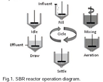
An SBR is composed of a single operation unit, which is equipped with different agitation and airing mechanisms, and active mud, which acts as the biological degrader of the organic material in the wastewater. The functioning of the reactor is sequenced in time, which implies that the entry of the wastewater, the airing phases, the agitation, and the unloading of the treated effluent, must be controlled according to the process requirements. A simple illustration of this sequencing in time is presented in Fig. 1, showing the processes that comprise the different stages carried out by the SBR system. These phases must be controlled and timed according to the experimentation requirements and, in some cases, may be executed simultaneously to achieve better contaminant removal efficiency, as is the case for the filling and reaction stages (airing – agitation). The control strategies are the main foundations for every automated system. For this reason, the development of the SBR –at a laboratory scale–, apart from establishing conventional sequenced control strategies for the processes and their timing [6], aimed to provide a wide array of configuration options that allow the treatment system to adjust to different wastewater matrices, so that it may improve the quality of the obtained effluent, which enables the system to treat contaminants with difficult degradations. This condition eases the reactor's capacity to treat different reactors than the ones it regularly treats.
The need to modify and define the process, where it is necessary to program the sequence of the phases that are to be followed and the required conditions as well as their timing and the cycles that must be repeated, has motivated the proposal of the following objective: the development of an automated system that is sufficiently versatile that it allows the operator to program a configuration that adjusts to the process' requirements.
Given the number of possibilities, the system must have hardware and software that adjusts to the experimentation requirements. It was determined that the following 4 digital exits are necessary: two solenoids for air entry and material unloading, one agitator, and a pump (for material entry). Additionally, the following 4 entries are needed: two level sensors (high-low), an initiation button, and a stop button.
The following section summarizes the different hardware and software components that were implemented, guaranteeing a flexible, reliable system, which allows the automation of different processes according to the needs of every test. 2.2 Description of the SBR System The first stage of the project consisted of the construction of an acrylic SBR reactor with a useful volume of 9.0 l, with an inner diameter of 15 cm, and a total height of 70 cm. This design and sizing was carried out according to the procedure proposed by Von Sperling and De lemosChernicharo, 2005 [7], using a feed rate of 45.83 ml/min and a DQO of 250 mg/L as a base. A circular geometry was used to favor the appropriate homogenization of the system in contaminant removal processes, while trying to avoid the formation of dead zones in the interior of the reactor. Additionally, a high height/diameter ratio was used to favor the separation process in the solid-liquid phases, so the treated effluent may be easily extracted, preserving the bio-solids that were generated I the organic matter degradation process inside the SBR.
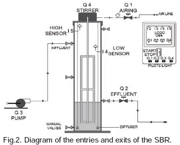
In the second stage, the reactor was equipped with sensor elements, a controller (LOGO) and actuators (motors, valves, peristaltic pumps) that enable the automation of the process. Fig. 2 illustrates the general diagram for the control of the SBR; each of the parts that it was equipped with is described later.
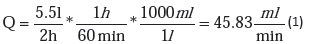
1) Peristaltic Pump: with a capacity of 6-600 RPM, a potency of 75 watts and a caudal (Q) between 0.36 – 3400 ml/min [8], used for the entry of synthetic wastewater whose caudal was calculated and adjusted to, taking into account the volume and the required time. See Equation (1).
2) Agitator: Heidolph RZR 2021 with a velocity range of 40 - 2.000 rpm and an output potency of 27 W[9], controlled with an electromagnetic relay connected to one of the LOGO exits.
3) Level Sensors: flotation ON-OFF switches, connected to one of the entries of the LOGO, enabling the operator to define the filling level (highlow).
4) Diffusion System: composed by a solenoid (connected to a pneumatic system), two manometers and diffusion stones. It supplies air depending on the process requirements.
5) Effluent Solenoid: it opens to decant the reactor. It is usually activated after the settlement stage, during a time that the user programs (which is enough to allow the solid particles to settle at the bottom of the reactor).
6) LOGO: controller in charge of the automation of the process, allowing the user to define and validate the required variables with the use of a software that was created specifically for the reactor. Note: all periferic elements actions are based on digital variables.
A Siemens logo OBA6 [10], [11], with the following characteristics was used for the automation of the process:
• Programmable with the LOGO!SoftComfortV7.0 Software.
• Entry tension of 115/240 V CA/CC.
• 8 digital entries.
• Exits with a maximum relay of 10 A.
• Visualization display for variable and conditions. Simplified keyboard for programming. Mainly used for relatively small programs.
This controller was chosen because it is equipped with a LOGO OBA6, which satisfies the entry/exit, timer, counter, screen, memory capacity requirements, apart from the reliability that the Siemens brand offers.
2.3 Software Description
Certain difficulties arose using the LOGO!SoftComfort and the ladder programming language, especially in two aspects:
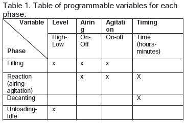
The need to define a set of parameters linked to the 4 phases of the process. The options for the different variables are summarized in Table 1.
The characteristics that the automated system requires made it necessary to take into account the following conditions:
Filling: Option for selecting the low or the high working level according to the flow rate, with the possible agitation, airing, airing-agitation or simple filling (without agitation or airing) combinations.
Reaction: Composed by two stages, each of which had time parameters (Hours/Minutes), airing (On/Off) and agitation (On/Off).
Decanting: the waiting time, when there is no actuator action, was defined (Hours/Minutes). Unloading: the opening time of the unloading solenoid.
Additionally, conditions were included for security, evaluation of problems that are external to the software (mainly jamming due to the liquid type), sensor errors, or erroneous parameter entry.
To fulfill the requirements, a program was designed using Petri Networks, and it was customized to the limitations of the selected LOGO.
• A second aspect was the set of limitations of the LOGO, which, being low end, restricts the programming possibilities. The following is a summary of some of the difficulties:
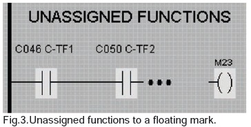
• If elements are inadequately deleted, ''fictitious'' contacts are created that prevent the program from running.
• If some special functions are used, the program prevents the transmission from the PC to the controller. In this case, contacts which activate a floating mark are created. The solution is illustrated in Fig.3:
The restriction of the LOGO!SoftComfort pertaining to the use of one exit for various instances limits the versatility of the programming, which made it necessary to redefine them to adjust to the software's limitations.
3. RESULTS: AUTOMATION.
The Petri Network technique was used to design the program [12], as it eases the programming process and allows agile and reliable implementation. Furthermore, a Petri network can be translated into PLC Ladder language using basic elements (contacts, coils, timers and counters) [13], [14], [15].
3.1 Petri Networks.
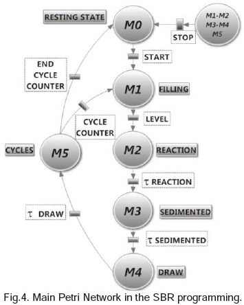
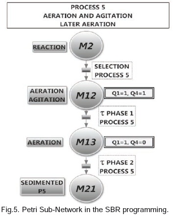
The program consists of a series of Petri networks that define the different phases. The main network is illustrated in Fig. 4, which identifies the four phases that model the process (filling, reaction, settlement, and decanting). Each of these phases is, in turn, implemented through sub-routines, one of which is illustrated in Fig. 5.
With the purpose of illustrating the process, part of the algorithm of the main network is detailed:
• MO: Resting state, during which all the system is off.
• Start: The transition is enabled when the Start button is pulsated, which activates the next state.
• M1: Filling state. During this state, it is possible to define the different options that the phase allows (see Table 1), which made it necessary to design a Petri Network that is consistent with the requirements.
• Level: When the corresponding level switch is activated (high or low), the transition is enabled, which allows the system to evolve into the new state.
• M2: Reaction. While the process is in this state, the system functions according to the conditions that are defined by the programmer; it corresponds to the Petri sub-network illustrated in Fig.5.
The evolution of the other states follows the same conditions that were previously presented.
Given the total Petri Network of the program is too extensive and taking into account the length of the paper, not all of the designed networks are presented. However, they do fulfill the necessary requirements in the process specification.
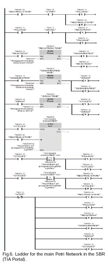
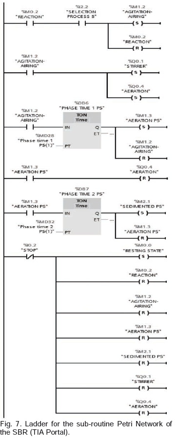
3.2 Ladder Programming.
With the intention to illustrate the implementation of Petri networks in the Ladder language, Fig. 6 and 7 present the programs that correspond to the networks that were presented earlier, as they are usually developed in conventional PLC programs (using the TIA Software Portal).
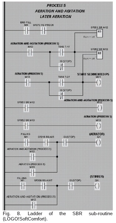
However, given the restrictions of working with a low-level system, this type of programming requires special considerations, as it does not allow the direct Petri-Ladder translation, which made it necessary to resize the program, making it compatible with the equipment (LOGO OBA6).
Fig. 8 presents one of the same Petri Networks (sub-routine) implemented in the LOGOSOFT.
3.3 Screen and Selection Keyboard.
The LOGO is equipped with an alphanumeric screen and a keyboard (6 keys), with which it is possible to program and offer a selection menu.
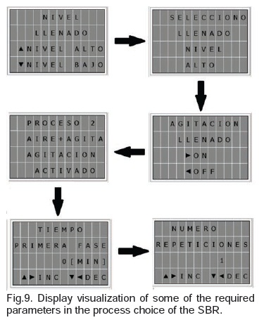
For the project, the system was programmed in such a way that it offers the operator the different alternatives for the process, choosing from an array of options. An example of this is briefly illustrated in Fig. 9.
4. DISCUSSION.
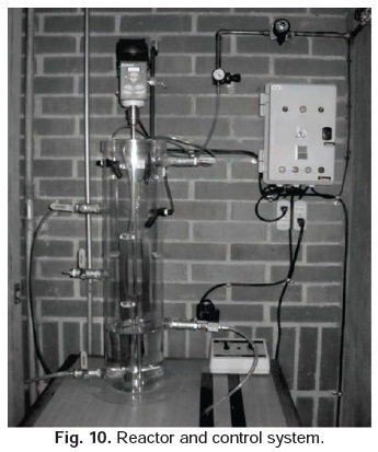
Fig.10 shows the implemented hardware system that resulted from the project, and the different parts of the system can be seen.
During the first stage of the project, a reactor was built with the required characteristics and it was conditioned with sensors, actuators and a control system, as can be observed in Fig. 10.
During the second stage, after the LOGO was programmed, the results were validated with tests in different operating conditions and scenarios.
4.1 Implementation and Launch of the Designed Program.
Once the programming difficulties caused by the limitations of the chosen LOGO were overcome, the program that was developed was loaded so its response could be evaluated. Each part of the system was evaluated using individual commands via the controller; afterwards, the conjunct operation was validated in different scenarios programmed with the keyboard/screen.
4.2 Evaluation.
The evaluation of the automated program implemented for the SBR System was based on the checkup of the 40 possible operation configurations that the user can employ each time he wants to run the system. These verifications showed a good response from the software in the operation during the small time intervals that were designated for each one of the phases being tested. However, during this evaluation, the need for the implementation of some adjustments was detected to allow the system to reach its optimal performance. The main adjustment was the option to ''Stop'', which enabled the user to stop the process at any given moment of the reactor's operation. Due to the conditions of the process, when the problems that instigated the stop are solved, the system returns to the initial state, preserving the organic matter. This aspect is not common in traditional processes, but is necessary considering the type of operation. Consequently, when the system is restarted, the conditions to pass to the M2 stage are generated.
The selection of each of the operating sequences for the reactor was carried out using the screen, via texts that guide the user in the configuration of multiple options that are displayed step by step each time the concerned applications are selected. These configurations may be checked using the LOGO screen once the program is running, allowing the system user to check the state of the process and the time that the reactor takes for each of the operation phases. Additionally, the control box was equipped with different colored pilots to enable the operator to determine the phase of the process that system is currently in without having to check the LOGO screen, merely observing the name of the pilot that is running.
5. CONCLUSION
The desired results of the project were achieved and the hardware and software objectives were accomplished.
Once the programming difficulties were overcome, the hardware was conditioned to fit the user's needs, while the final program turned out to be versatile, reliable, easy to determine parameters, and to operate, enabling its reconfiguration for other processes. Additionally, the graphic options gave further ease to the selection of parameters, using the keyboard and the LOGO display, according to the options that the process required.
As for the texts, a petition sequence permitting the choice of different parameters was made, and as the parameters are chosen, a confirmation text is generated.
The technology was optimized using automation. In this particular case, it shows that it is possible to use a low-end controller and obtain the same results that a medium-rate controller achieves through software conditioning. This minimizes costs and simplifies hardware requirements.
Finally, traditional control strategies for SBR systems have been limited to the sequenced control of the established processes and the duration of the different operation phases of the reactor. This is why this project offered an array of 40 configuration options for the sequenced operating phases, which can be established by the operator, allowing the system to adjust to different matrices of wastewaters, thus accomplishing the quality of the desired effluent. Additionally, in the field of research, it is possible to optimize the system by modifying the phases and the operating times for the removal of specific contaminants, which can be persistent and of difficult degradation.
This condition allows the reactor to adjust to the treatment of different contaminants, which makes it possible to increase the system's applications in the future, with the development and optimization of the technology and the advance in the fields of automation and control.
6. ACKNOWLEDGEMENTS
The authors thank the GDCON team, the GIMEL team, and the 2014-2015 Sustenance Fund of the Research Vice-Rectory of the Universidad de Antioquia for financing this project.
7. BIBLIOGRAPHY
[1] Brausch, J. M. y Rand, G. M..A review of personal care products in the aquatic environment: Environmental concentrations and toxicity, Chemosphere, vol. 82, pp. 1518–1532, 2011.
[2] Chan, Y. J.,Chong, M. F.,Law, C. L., y Hassel, D. G. l. A review on anaerobic–aerobic treatment of industrial and municipal wastewater, Chem. Eng. J., vol. 155, no. 1–2, pp. 1–18, Dec. 2009.
[3] Fernandes, H., Jungles, M. K., Hoffmann, H., Antonio, R. V. y Costa R. H., Full-scale sequencing batch reactor (SBR) for domestic wastewater: Performance and diversity of microbial communities, Bioresour. Technol., vol. 132C, pp. 262–268, Jan. 2013.
[4] Malakahmad, A., Hasani, A., Eisakhani, M., y Isa, M. H., Sequencing Batch Reactor (SBR) for the removal of Hg2+ and Cd2+ from synthetic petrochemical factory wastewater, J. Hazard. Mater., vol. 191, no. 1–3, pp. 118–25, Jul. 2011.
[5] Casellas, M., Dagot, C., yBaudu, M., Set up and assessment of a control strategy in a SBR in order to enhance nitrogen and phosphorus removal, Process Biochem., vol. 41, no. 9, pp. 1994–2001, Sep. 2006.
[6] Yang, Q., Wang,S.,Yang, A.,Guo, J., y Bo, F., Advanced nitrogen removal using pilot-scale SBR with intelligent control system built on three layer network, Front. Environ. Sci. Eng. China, vol. 1, no. 1, pp. 33–38, Feb. 2007.
[7] VonSperling, M., De lemosChernicharo, C. A.,Biological Wastewater Treatment in warm Climate Regions., C. V. Andreoli& F. Fernandes,Eds., (p. 1459). London: IWA Publishing.
[8] Masterflex L/S variable-speed modular drive, 6 to 600 rpm, 115 VAC. Disponible en: http://www.masterflex.com/Product/Masterflex_L_S_variable_speed_modular_drive_6_to_600_rpm_115_VAC/HV-07553-70#Specs [consultado el 26 de septiembre de 2014].
[9] Heidolph RZ2021. Disponible en: http://www.heidolphinstruments.com/products/overheadstirrers/mechanical-stirrers/rzr-2021 [consultado el 26 de septiembre de 2014].
[10] BELTRÁN, Francisco F; et al. ''Funciones Lógicas en el Relé LOGO! de Siemens''. Universidad Pontificia Bolivariana. http://kosmos.upb.edu.co/web/uploads/articulos/(A)_Recurso_de_AutoAprendizaje_Tecnologia_Fluidica_Funciones_Logicas_en_el_Rele_LOGO_de_Siemens_1608.pdf. [consultado el 26 de septiembre de 2014].
[11] LOGO! Manual. A5E01248535--01. Siemens, Jul.2008. http://www1.siemens.cz/ad/current/content/data_files/automatizacni_systemy/mikrosystemy/logo/zakladni_pristroje/_manualy/manual_logo-0ba6_07-008_en.pdf. [consultado el 26 de septiembre de 2014].
[12] Uzam, M., Jones, A. H.,Discrete Event Control System Design Using Automation Petri Nets and their Ladder DiagramImplementation,The international journal of advanced manufacturing Technolog(1998) 14:716-728. © Springer-Verlag London Limited, 1998. 716-728.
[13] Perme, Tomaž. Translation of Extended Petri Net Model into Ladder Diagram and Simulation with PLC, Strojniskivestnik - Journal of Mechanical Engineering 55, 2009, 608-622.
[14] Vásquez Salazar, Rubén Darío. ''Control lógico programable''. ITM, 1a.edición: diciembre de 2010. [15] Gergely, EugenLoan; Coroiu, Laura; Gacsadi, Alexandru, Design of Safe PLC Programs by Using Petri Nets and Formal Methods. Recent Advances in Automation &Information.ISBN: 978-960-474-193-9.