ARTICLES
STATIC COMPENSATORS ASSESSMENT IN THE WIND POWER SYSTEMS TRANSIENT STABILITY WITH INDUCTION GENERATORS IN DISTRIBUTION NETWORKS
EVALUACIÓN DE COMPENSADORES ESTÁTICOS EN LA ESTABILIDAD TRANSITORIA DE SISTEMAS EÓLICOS CON GENERADORES DE INDUCCIÓN EN REDES DE DISTRIBUCIÓN
Luis Zapata1, Esteban Velilla2, Jesús María López Lezama3
1 Electrical Engineer, University of Antioquia. E-mail: luis.a.z.g@gmail.com.
2 Master in Electrical Engineering, GIMEL Group, Department of Electrical Engineering, University of Antioquia, E-mail: esteban.velilla@gmail.com.
3 Ph.D. in Electrical Engineering, GIMEL Group, Department of Electrical Engineering, University of Antioquia, Calle 70 No 52-21, Medellín, Colombia. E-mail: jesusmarialopezl@gmail.com.
Recibido: 12 de septiembre de 2014. Aceptado: 20 de octubre de 2014.
Received: September 12th, 2014. Accepted: October 20th, 2014.
ABSTRACT
Currently, most wind power plants use induction generators in their operation. Due to their nature, these generators are usually equipped either with static or dynamic compensation devices. This paper presents an assessment of the use of static compensators in the stability of wind induction generators. To perform the study, a base case was used in which a three-phase fault that destabilizes the network is simulated. Then, to stabilize the network and avoid an eventual disconnection or damage of the wind power farm, three compensation alternatives were considered: capacitors, STATCOM and SVC. The effectiveness and performance of each of these alternatives were evaluated. Simulations were carried out in Simulink of MATLAB@, showing satisfactory results for the compensation alternatives under study. The performed simulations identified the STATCOM with IGBT as the most effective compensation under eventual contingencies. On the other hand, it was found that all the studied alternatives are equally effective for voltage compensation in steady state conditions.
Key words: stability, static compensators, induction generators, wind farms.
RESUMEN
En la actualidad la mayoría de los parques eólicos utilizan generadores de inducción para su operación. Debido a su naturaleza, estos generadores normalmente son equipados con elementos de compensación que pueden ser de naturaleza estática o dinámica. En este artículo se presenta una evaluación del uso de compensadores estáticos en la estabilidad de sistemas eólicos equipados con generadores de inducción. Para el estudio se utilizó un sistema base sobre el cual se simula una falla trifásica que desestabiliza la red. Posteriormente, para estabilizar la red y evitar una eventual desconexión o daño del parque eólico, se consideraron tres alternativas de compensación: condensadores, STATCOM y SVC. Las simulaciones fueron realizadas en la herramienta Simulink de MATLAB@, mostrando resultados satisfactorios para las alternativas de compensación estudiadas en cuanto a su desempeño y eficacia. Las simulaciones realizadas permitieron identificar al STATCOM con IGBT como la compensación más efectiva frente a eventuales contingencias. Por otro lado, se encontró que todas las opciones estudiadas son igualmente efectivas para la compensación de tensión en régimen de estado estable.
Palabras clave: estabilidad, compensadores estáticos, generadores de inducción, parques eólicos.
1. INTRODUCTION
Wind turbines directly convert wind energy into mechanic energy that triggers an electric generator. Currently, wind generators have a capacity that ranges from a few kW (such as the ones used for households) to several MW. The generators that have the latter capacity can be grouped in high capacity wind power plants for a centralized generation of power. The configuration of the wind generators may vary according to the direction of the rotating axis (horizontal or vertical), their operation (fixed velocity or variable velocity), their use of converters and the type of electric generator [1].
Most wind power plants are equipped with induction generators, which require a capacitive reactive power for their proper operation. This power is usually taken from the network. However, in predominantly inductive networks, there is no way that the network can generate the capacitive reactive power, which is one of the main reasons why reactive power compensation devices are used in wind power plants. These compensation devices inject capacitive reactive power to balance the inductive effect of the induction generators; alternately, the compensators can inject inductive reactive power according to the network's regular behavior. Additionally, you can regulate tension and the connection point power factor with these devices.
Reactive power compensation can be achieved with the use of static equipment (compensation banks and FACTS among others) or dynamic equipment (rotation devices). FACTS (Flexible AC Transmission Systems) are elements that are based on power electronics and static controllers to increase the power and improve power transfer capacity. These devices redirect the power flow in a way that improves the use of the stability network. Among the FACTS is STATCOM (Static Synchronous Compensator), which enables control of the power flow and improves the transitory stability of a network. The STATCOM regulates the tension in its terminals, thus controlling the amount of reactive power injected or absorbed by the power system [2]. When the system's tension is low, the STATCOM generates reactive power (capacitive STATCOM); when the tension of the system surpasses certain value, it absorbs reactive power (inductive STATCOM).
Another element in the FACTS family is the SVC (Static Var Compensator). This device is a static reactive power generator, whose output varies with the intention of maintaining a specific control over certain variables (tension, frequency, power factor) of an electric power system. Reactive power variation is carried out through the commutation of a three-phase capacitor and inductor bank, connected to the secondary coupling transformer [3].
The stability of an electric power supply system can be defined as the property of the system that allows it to remain in a balanced state of operation under regular circumstances and regain an acceptable state of equilibrium after being subject to a disturbance [4]. Given their importance in the continuity of the electric power supply, stability problems in power systems are widely studied. Item [5] is a critical revision of some of the approaches of stability tension studies that have been used since the 1960's until our time. Item [6] is a study on the transitory stability of industrial systems with distributive generation. Item [7] is a dynamic analysis of tension stability considering unbalanced charges.
In general, the tendency to produce electricity with clean energy, such as wind power generation, presents new challenges for stability studies. The problems that may be caused by the increase in wind power generation with induction generators also affect short-circuit levels, harmonics generation, and tension and frequency regulation, as illustrated in [8] and [9]. Item [10] is a presentation of different control strategies for FACTS devices connected in a derivative way (STATCOM and SVC) to improve the quality of the power generated in wind power plants. Item [11] is a control strategy for small wind power parks to supply reactive power and improve transitory stability. Other studies about FACTS devices and their impact on the stability of induction generators are showcased in items [12] and [13].
The inappropriate operation of induction wind generators can have a negative impact on the transitory stability of the system, and also on the variation of the nominal tension of the connection point of the wind power park. This paper evaluates the performance of different alternatives of static compensation in a distribution system for a wind power plant. The alternatives which were considered involve capacitor banks, STATCOM and SVC. Through simulations, the efficiency of these compensation alternatives to improve tension levels and system stability was verified, and they were contrasted.
2. MATERIALS AND METHODS
TEST SYSTEM
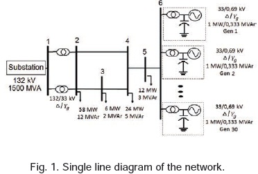
The network is a distribution system with 6 (bars), a 132kV feed through 2 parallel 132/33kV transformers connected at Δ/Y, Fig. 1 [14]. On bus 6, a wind generation park with a capacity of 30MW, and composed of 30 generators is installed. These 30 generators are 1MW squirrel-cage type generators, with a type A, 2-pole turbine (a fixed velocity turbine) that has a stator resistance and inductance of 0.010 and 0.100pu, respectively, a magnetization inductance of 3.5pu, and an inertia constant of 1.4. The wind generation park is connected directly to the network through a transformer that elevates the tension from 690V to 33kV.
The wind power plant is modeled through the SimPowerSystem ''Wind Turbine'' block. The following input parameters were considered:
Wind velocity: 9m/s (value obtained from the SimPowerSystem power curve, which is determined according to each turbine, and is defined as the minimum velocity needed to reach the generator's nominal velocity); the reason between the tangential velocity of the point of the asp (ωr) and the incident wind velocity (λ): 8.1; and the passing angle (β): 0O.
The output arguments are defined as the mechanical torque (Tm) for the trigger of the induction generator and the mechanical power generated by the turbine (Pm).
To obtain a diagnosis of the test system and confirm the operation point in (a stable state) of bus 6 (where wind power generation takes place), a power flow was calculated. According to norm ANSI C84.1 [15], the magnitude of the tension in all buses for this type of distribution system must be superior to 0.95pu. However, after calculating the power flow, it was discovered that the tension in bus 6 was 0.884pu. This is due to the fact that the induction generators have a high reactive power consumption that affects the tension level negatively at the connection point. Consequently, it is necessary to use some form of compensation to maintain the tension in bus 6 within an adequate range.
VELOCITY AND CRITICAL TIME IN INDUCTION GENERATORS
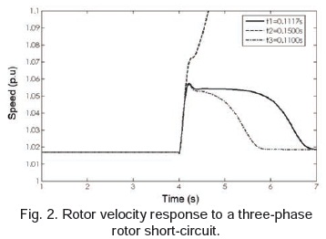
When there is a short circuit in the network, the induction generators tend to accelerate due to an abrupt reduction of the electric torque. Stability in the face of great disturbances in the induction generators can be determined by analyzing the time response of the rotor's velocity after a short circuit.
The instability will depend on the clearance of the fault, for it must be eliminated before the rotor reaches its maximum critical velocity. The critical time of the fault elimination is defined as the time in which the system, when a fault occurs, may or may not return to a stable operation point [16]. If the fault is eliminated, then the system may return to a stable state. Figure 2 shows rotor velocity for different clearance times for a three-phase fault. It can be observed that the breakers must act in a maximum time of 0.1500s (critical time). If more time goes by, the system will not return to a stable state.
The electro-mechanic equilibrium of an induction generator is given by Expression (1).
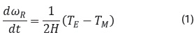
Where TM is the mechanic torque, H is the inertia constat, TE is the electric torque, and ωR is the generator's rotor velocity.
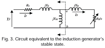
The electric torque of the induction generator may be represented in function of the rotor's resistance (RR), the sliding (S), and the rotor current (IR), as the equation illustrates (2). Figure 3 illustrates the circuit that is equivalent to the induction generator's stable state. From this circuit, considering the Thevenin equivalent between points a and b, Equations (3), (4) and (5) can be obtained [16]. On the other hand, the rotor sliding is calculated with expression (6).
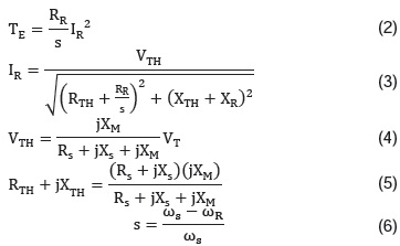
Where Rs is the stator resistance, RTH is the Thevenin resistance of the circuit equivalent to the generator, RR is the rotor resistance, Xs is the stator resistance, XR is the rotor reactance, XM is the magnetic reactance, ωs is the system's synchronic velocity, ωR is the rotor velocity, and s is the rotor sliding.
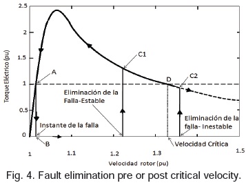
The solution to the differential equation (1) corresponds to the points where the electric torque is the same as the mechanic torque. By solving the equation, results for points A and D, shown in Fig. 4, can be obtained. Point A represents the stable state of the machine, the point of the generator's normal functioning. Point D corresponds to the critical time or critical velocity, which is the maximum return point for the system to return to stability.
There are two moments that must be evaluated to understand the dynamics of the fault and the importance of compensation. When the fault occurs, tension in the affected bus tends to zero, thus, the electrical torque will also have this behavior according to the relation shown in (2) and (3), reaching point B in Fig. 4. Consequently, the velocity will increase, because there is a difference between the torques (see Equation (1)). This increase will continue until torque stability is reached once more. If the fault is cleared or eliminated before reaching Point D, Characteristic C1, the torque will continue the trajectory of the curve that was shown, with torque and velocity increase, but returning to Point A stability. On the contrary, if the protections isolate the fault after Point D, Characteristic C2, the electric torque will follow the behavior of the dotted curve, which is why there will not be balance between the torques, and according to the relation between the electric and the mechanic torque, the velocity will continue to increase until the difference is zero, making the system unstable.
3. RESULTS AND DISCUSSION
As it was mentioned before, the system that was illustrated in this case needs a compensation method to improve tension levels. If a compensation element is installed, from a mathematical point of view, it equals to the modification of equations (3), (4) and (5), and, consequently, equations (1) and (2). This occurs because, in general, the compensation reduces the inductive portion of the equivalent circuit. Thus, the equivalent impediment is smaller, and, consequently, the tension and power magnitudes tend to increase (because the electric torque grows with the current, squared). The effect is equivalent to displacing the curve in Fig. 4 upwards, displacing Point D towards the right.
The objective of the compensation in this case is to increase the electric torque, increasing the critical time for fault clearance. In the simulations that were carried out, the rotor velocity was monitored to determine if the system could regain its stability. Additionally, the tension and the reactive power were evaluated with the intention of determining the effectiveness of each of these controls to have judgment calls for the eventual selection of some of these.
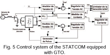
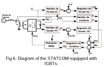
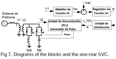
The compensation methods used for the study were: a 15MVar capacitor bank, a STATCOM with GTO (GateTurn-Off Thyristors), illustrated in Fig. 5, a STATCOM with IGBT (InsulateGate bipolar transistor), illustrated in Fig. 6, and an SVC, illustrated in Fig. 7. Although there are other compensation methods, these 4 types were selected because they are the most commonly used and because they had good performances with different types of testing system faults, as reported in [17]. The compensation methods are briefly described in the following paragraphs. A detailed description of the control systems of these devices is beyond the reach of this document, but may be found in [13].
The STATCOM regulates the tension in its terminals by controlling the amount of reactive power injected or absorbed from the power system. The reactive power variation is carried out by means of a VSC (Voltage Source Converter), which is connected through a coupling transformer. The VSC uses electric power devices with a forced commutation (GTO, IGBT o IGCT) to synthesize or transform the tension of the source of DC tension.
The STATCOM with GTO uses square wave inverters with GTO and an interconnection with special transformers (zigzag). 3-level converters are regularly used to generate a square wave of 48 pulses. The interconnection with special transformers is used to neutralize the harmonics contained in the square wave shape, which are generated by the individual inverters.
The control system uses the following modules: Phase Lock Loop (PLL): synchronizes the pulses of the GTO towards the tension system and generates the reference angle for the measurement system. Measurement system: Calculates the components of the positive sequence of the tension and the current for the STATCOM, using dq0.
Tension regulator: The tension regulator block calculates the reactive current Iqref reference using the current regulator block.
Pulse generator: Generates the pulses of the four inverters in the PLL output and of the current regulator.
The STATCOM with IGBT, which uses PWM inverters based on IGBT, figure 7. These inverters use the Pulses-WidthModulation technique to synthesize the shape of the sinusoidal wave of the DC tension source with a chopping frequency of a few KHz. The harmonics that are generated by the controller are eliminated with filters that are located in the AC of the VSC.
The SVC varies the reactive power be means of the switching of a three-phase capacitor bank and a bank of inductors connected secondarily to a coupling transformer. Each capacitor bank is turned on or off by switches from three thyristors.
The utility or advantage of the SVC is its capacity to change its capacitance-inductance to a high velocity, making use of potency electronics.
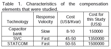
Table 1 illustrates some of the characteristics of the compensation elements that were used, taking into account that from economic point of view, the STATCOM is the most expensive option, and the capacitor bank is the least expensive, although its response velocity is slow.
3.1 Rotor Velocity
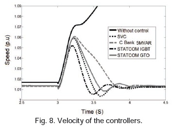
To evaluate the effectiveness of the controls, a three-phase fault is projected in the 2-4 at t=3s. Fig. 8 illustrates the rotor velocity response vs. the time it takes to implement each of the controls that are being studied. As you can observe, the most effective control (that takes the least amount of time to make the system return to stability) is the STATCOM with IGBT, which took approximately 960ms to return the system to a stable state. On the other hand, the slowest control was the capacitor bank, which took 1150ms to stabilize the system. If the aim was to reduce the stabilization time with the capacitor bank, it would require an increase in capacity, because as capacity increases, the stabilization time decreases.
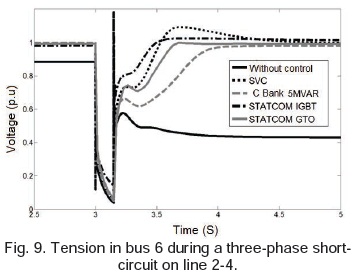
3.2 Tension Control
Figure 9 illustrates the response of the tension on bus 6 when the three-phase fault occurs. It can be observerd that the 4 controls are effective, because the tension in bus 6 before and after the fault remains around 1pu. However, if the specific value of the voltage is evaluated, the STATCOM with IGBT has the best performance, guaranteeing a stable tension of 1.007pu. In second place is the SVC, which guarantees a tension of 0.994pu. Then came the STATCOM with GTO with a tension of 0.991pu, and finally the capacitors, with a tension of 0.98pu. With the current capacity of the capacitor bank (15Mvar), it is not possible to obtain a tension of 1.0pu; to obtain that value, a 17Mvar capacitor bank would be needed.
To fulfill the ANSI C84.1 norm, the tension in the system at a stable state should be equal to or greater than 0.95pu. As it is illustrated in Figure 9, the response from all of the controls fulfills the norm, meaning that the tension variable would not determine the selection of the controller. However, it is clear that the control with the IGBT has the best response, as it is the only one that guarantees a terminal tension magnitude above 1pu. On the other hand, when the tension on bus 4 (near the generator park), it can be observed that all the controls except the STATCOM with GTO still guarantee a tension over 0.95pu.
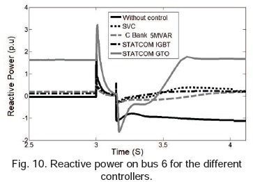
If the objective of the study is to control the tension of the bus where the compensating element is installed, it is necessary to evaluate the performance of other variables in the network. Figure 10 illustrates the reactive power on bus 6 (where the control is installed). It can be observed that the STATCOM with GTO injects a great amount of reactive power to maintain the tension near 1pu, while the others make the power in the bus approximately 0 (power factor close to one). The capacitor bank, the SVC and the STATCOM with IGBT not only regulate the tension, they improve the power factor on the installation bus. Fig. 10. Reactive power on bus 6 for the different controllers.
4. CONCLUSIONS
This article presents an evaluation of the performance of four types of static compensators in case of great disturbances in wind power generator systems that are equipped with induction generators. In terms of the improvement of the tension, the effectiveness of the 4 options that were proposed (capacitor banks, SVC and STATCOM with IGBT and GTO) was confirmed, meaning that they would all maintain the tension in appropriate ranges. On the other hand, in case of a contingency of a line near the generator park, simulations allowed us to conclude that the best compensation is achieved with the use of a STATCOM bank IGBT.
In this same scenario, the capacitor bank is the option that takes the most time to return the system to a stable state. However, when the capacity of the capacitor bank is increased, the system can return to its stable state in less time. Finally, it was confirmed that the capacitor bank, the SVC and the STATCOM with IGBT, apart from regulating the tension, improve the power factor of the installation bus. In general terms, one can say that the STATCOM excels the capacitor bank, but it is the most expensive option, which is why the person in charge of planning the distribution network must take into account different criteria when the time comes to make a decision about what compensator to use.
5. BIBLIOGRAPHY
[1] Martínez, F., De Pablo, S., y Herrero, L.C., Emulador de lazo abierto para turbinas eólicas de paso fijo, Revista Inf. Tecnol.Cit., 22, 85-94, 2011.
[2] Wessels, C., Hoffmann, N., Molinas, M., and Fuchs, F.W., StatCom control at wind farms with fixed-speed induction generators under asymmetrical grid faults, IEEE Transactions on Industrial Electronics, 60, 2864-2873, 2013.
[3] Teleke, S., Abdulahovic, T., Thiringer, T., and Svensson, J., Dynamic performance comparison of synchronous condenser and SVC, IEEE Transactions on Power Delivery, 23, 1606-1612, 2011.
[4] Kundur, P., Power Systems Stability and Control, 2a Edición, McGraw-Hill, New York, Estados Unidos, 1993.
[5] Candelo, J.E., Caicedo, G., and Castro F., Métodos para el estudio de la Estabilidad de Voltaje en Sistemas de Potencia, Revista Inf. Tecnol. Cit: 22, 85-94 2011.
[6] Trebilcock M.F., Santamaría, F., y Alarcón, J.A., Análisis de estabilidad transitoria en un sistema industrial con generación propia interconectado en el sistema de potencia, Revista Inf. Tecnol.Cit: 25, 77-84 2014.
[7] Correa, R.E., y Collado, J., Inestabilidad de Voltaje en Sistemas de Potencia, Revista Inf. Tecnol.Cit: 17, 147-155, 2006.
[8] Muljadi, E., Butterfield, C.P., Parsons, B and Ellis, A., Effect of variable speed wind turbine generator on stability of a weak grid, IEEE Transactions on Energy Conversion, 22, 29-36, 2007.
[9] Gautam, D., Vittal, V., and Harbour, T., Impact of increased penetration of DFIG-based wind turbine generators on transient and small signal stability of power systems, IEEE Transactions on Power Systems 24, 1426-1434, 2009.
[10] Olmanei J., Javan J. Yavartalab, A y Khederzadeh M. Advanced Control of FACTS devices for improving power quality regarding to wind farms, Energy Procedia, 4, 298-303, 2012.
[11] Mehdi Samiei Sarkhanloo, Ahmad Sadeghi Yazdankhah, y Rasool Kazemzadeh. A new control strategy for small wind farm with capabilities of supplying required reactive power and transient stability improvement. Renewable Energy 44, 32- 39, 2012.
[12] Senthil Kumar N., and Gokulakrishnan J. Impact of FACTS controllers on the stability of power systems connected with doubly fed induction generators. International Journal of Electrical Power & Energy Systems, 33, 1172-1184, 2011.
[13] Kenan, Dösoglu, M., Ali Öztürk. Investigation of different load changes in wind farm by using FACTS devices. Advances in Engineering Software. 45, 292-300, 2012.
[14] Barbosa, M., Análise do desempenho dinâmico de geradores eólicos conectados em redes de distribuição de energía elétrica, [Msc Tesis]. Campinas: UNICAMP, 1996.
[15] ANSI C84.1: American National Standard for Electric Power Systems and Equipment - Voltage Ratings (60 Hertz), National Electrical Manufacturers Association, United States of America, 2006.
[16] Grilo, A.P., Mota, A.d.A., Mota L.T.M., and Freitas, W., An Analytical Method for Analysis of Large-Disturbance Stability of Induction Generators, IEEE Transactions on Power Systems 22, 1861- 1869, 2007.
[17] Zapata Giraldo L.A. Estabilidad de generadores eólicos de inducción conectados en redes de distribución. Trabajo de Grado. Universidad de Antioquia, Medellín Colombia. 2013.