CONTROL OF THE MAXIMUM POWER POINT OF A SOLAR PANEL, USING SERVO SYSTEM CONTROLLER WITH INTEGRATOR AND PI CONTROLLER DESIGNED BY THE ROOTS LOCUS METHOD
Diego Alejandro Herrera-Jaramillo, MSc1; Luis Eduardo Garcia-Jaimes2; Maribel Arroyave-Giraldo3; Habib Elam-Escudero4
1Magister en Automatización y control industrial, Coordinador de investigación, Institución Universitaria de Envigado, daherrera@correo.iue.edu.co
2Magister en Educación, Especialista en Automatización Industrial, docente investigador Politécnico Colombiano Jaime Izasa Cadavid, luisgarcia@elpoli.edu.co
3Magister en Automatización y control industrial, docente investigadora, Institución Universitaria de Envigado, marroyave@correo.iue.edu.co
4Ingeniería Electrónico en formación, Institución Universitaria de Envigado. heescudero@correo.iue.edu.co
ABSTRACT
Photovoltaic system applications require to use a solar panel, a power converter, and a load. When voltage reduction from a panel to a battery is necessary, a buck converter is usually proposed. In the specialized literature, there are a wide variety of controllers oriented to commercial panels; However, even though measuring the energy extraction of a solar panel is the main indicator, there are other metrics such as switching effort that also affect the overall performance of the PV system. The main contribution of this work is the design of two digital controllers for photovoltaic energy extraction: a servo system controller with integrator and a PI controller based on root locus techniques considering an MPPT algorithm and system perturbations to demonstrate the reliability and efficiency of the controllers under different system scenarios.
Keywrods: PV system model, Buck converter control, RLM control, Servo-type control, MPPT algorithm

Recibido: 08 de Noviembre de 2023Aceptado: 25 de Enero de 2024
Received: November 08, 2023Accepted: January 25, 2024
CONTROL DEL PUNTO DE MÁXIMA POTENCIA DE UN PANEL SOLAR, UTILIZANDO CONTROLADORES TIPO SERVO CON INTEGRADOR Y CONTROLADOR PI DISEÑADO MEDIANTE EL MÉTODO DEL LUGAR DE LAS RAÍCES
RESUMEN
En aplicaciones de sistemas fotovoltaicos se requiere utilizar un panel solar, un convertidor de potencia y una carga. Cuando es necesario adecuar el voltaje de un panel a una batería, generalmente se propone un convertidor reductor. En el estado del arte, se encuentran gran variedad de controladores orientados a paneles comerciales; sin embargo, a pesar de que medir la extracción de energía de un panel solar es el indicador principal, existen otras métricas como el esfuerzo de conmutación que también afectan el rendimiento del sistema fotovoltaico. La principal contribución de este trabajo es el diseño de dos controladores digitales para la extracción de energía fotovoltaica: un controlador tipo servo con integrador y un controlador PI basado en técnicas del lugar geométrico de las raíces que consideran un algoritmo MPPT y perturbaciones del sistema para demostrar la confiabilidad y la eficiencia de los controladores bajo diferentes escenarios del sistema.
Palabras claves: Modelos de sistemas PV, convertidores Buck, control RLM, Control tipo servo, Algoritmo MPPT
Cómo citar este artículo: D. Herrera, L. Garcia, M. Arroyave, H. Elab. “Control of the maximum power point of a solar panel, using servo system controller with integrator and pi controller designed by the roots locus method”, Revista Politécnica, vol.20, no.339 pp.183-195, 2024. DOI: 10.33571/rpolitec.v20n39a13
1. INTRODUCCIÓN
Due to the exponential growth of photovoltaic (PV) installation worldwide, the scientific community has addressed the issue of optimizing energy production and reducing the costs of this technology. However, its efficiency is strongly affected by climatic factors such as temperature, irradiance, and partial shading [1]; these perturbations directly affect the maximum power point (MPP) tracking strategy, so keeping the PV at this point proposes to find a robust solution to any disturbance of this nature [2]; typically, MPPT techniques are used in solar systems to extract the maximum power regardless of the current climatic [3].
There is a large state of the art around control strategies and power converters implemented to regulate energy in PV systems, including classic linear strategies such as PID in different DC-DC converter types [4,5], as well as nonlinear strategies such as sliding mode control (SMC) [6-8], intelligent neural networks [9,10] and adaptative control strategies [11]. However, some of these controllers require an analog implementation that can significantly increase its costs. In parallel, embedded system programming technology has reduced the gap between analog and digital system implementation [12], thereby it is simpler the use of such devices to control electrical systems that require processing speed.
Also, there are numerous reports on proposed controllers for PV systems and a pulse width modulated (PWM) switched converter [13,14]. Similarly, different control strategies have been compared for the same system, exposing the facilities and difficulties that each strategy presents for a specific system; for example, the use of a buck-boost converter to regulate the transfer of power from a solar panel to a DC bus voltage [15]. On the other hand, PI and servo type controllers have been applied for PV systems that require an inverter stage; this, through pole placement, ensuring compliance with the design criteria for the controller.
Recently, there is an interest from the specialized scientific community in detailing the different control strategies and architectures of PV systems present in the state of the art, as mentioned in [16], which presents a comprehensive report on the advances in control strategies for different PV configurations with power converters, mentioning that each configuration is unique and therefore an appropriate design is required. On the other hand, the work of [17] details a review of the topologies applied for PV systems aimed at interconnecting DC buses.
Given the above, there are a large variety of control strategies to proper regulate the extraction of energy from a PV panel, considering the integration into electricity distribution networks that supply energy to industrial users, allowing to significantly reduce operating costs and increase competitiveness in productive sectors. In this context, solar PV systems could satisfy a significant percentage of the electricity needs of industrial companies in a cost-effective and reliable way [18],[19].
For this reason, each PV system requires a precise control strategy design to regulate the transferred energy as addressed in this work; to achieve it, a 210W PV system linked to a 12V DC bus is proposed. Such a methodology considers the design and evaluation of two digital control strategies developed in Matlab/Simulink®, considering environmental disturbances for a commercial PV model; additionally, the need to tune the MPPT algorithm for each proposed control strategy is evidenced. The article is divided into six sections, the first one being the introduction, followed by the proposed electrical model on which both. The MPPT algorithm and the control strategies will be evaluated together. As the third section, the description of the proposed MPPT algorithm, the fourth section explains in detail the analysis of the control strategies designed as the fifth section the discussion of the results and finally the conclusions of this work.
2. MATERIALS AND METHODS
The proposed system consists of a PV panel connected to a DC microgrid through a buck converter allowing to regulate the energy extracted from the renewable source. To represent it, there are different proposals in the specialized literature, such as, the Single Diode Model (SDM) [20] or the Double Diode Model (DDM) [21]. These models are notable for their accuracy in representing the dynamic response of a PV module along its P-V curve, some are more suitable for low irradiances and others for high irradiances. However, due to the accuracy reported by these models, control strategies also become more complex in the presence of non-linear variables. For this reason, linear approximations like the Norton equivalent circuit becomes a suitable solution given its simplicity in representing the behavior of a PV panel around an operating point [22]. Therefore, as shown in Figure 1 the Norton model is adopted (SDM), which considers a current source with the short circuit current (I_sc) of the PV panel, in parallel the resistor (R_pv) which is calculated as shown in Equation (1).
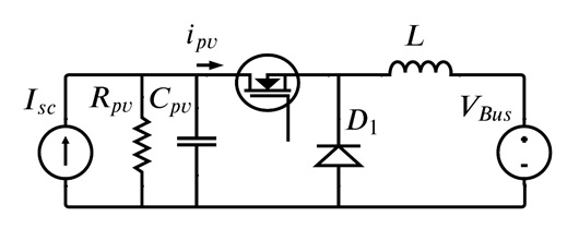
Figure 1. Buck converter interfacing a PV module and a DC bus.
 (1)
(1)
Where V_mp and I_mp correspond to voltage and current at maximum power respectively. Subsequently, an ideal buck-type step-down converter is proposed and connected to a DC bus which is represented by a DC voltage source describing the voltage regulated by an external control strategy; thus, the voltage is constant. In addition, for the system to operate around the maximum power point, it is necessary to monitor the performance of the PV module, to find the optimal operating point for the current environmental conditions by means of an optimization algorithm [23]. For this case, the perturb and observe (P&O) algorithm is proposed, which has been widely adopted by different control methodologies due to its simplicity and ease of implementation [24].
2.1. Mathematical model of the proposed system.
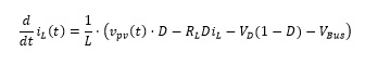
Due to the need to regulate the energy extracted from the PV system, the interest in modelling the behavior is centered on the capacitor current C_pv and the inductor voltage L; furthermore, the inductor 〖(R〗_L=0.1 Ω) and diode (V_D = 0.8V) losses are included to provide a refined approximation. In this way, Equations (2) and (3) describe the dynamics of the switched model, which are presented below.
 (2)
(2)
 (3)
(3)
To obtain the averaged model of the system, the signal S(t) is replaced by the duty cycle (D); in this way, the ripple product of switch switching is replaced by its average. For this reason, Equations (4) and (5) are modified as shown below.
 (4)
(4)
 (5)
(5)
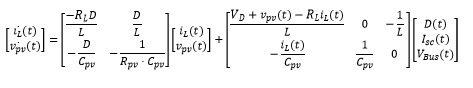
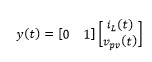
Taking as state variables i_L (t) and v_pv (t) furthermore, as input u=D, the linearised system in state space is defined by Equations (6) and (7)/p>
 (6)
(6)
 (7)
(7)
3. Controller design
Once the mathematical model of the system has been established, two control strategies are calculated using pole placement, the first using the root locus method (RLM) and the second using a servo system with integrator controller and full order observer. In both control strategies the poles are placed under the same time response specifications. In both cases, the panel voltage is controlled using the values estimated by the P&O algorithm as a reference.
3.1 PI controller design with RLM
This method can be used in the design of continuous or discrete controllers, when it is desired to locate the dominant closed-loop poles at a certain position and the system performance specifications are known, in terms of the transient response such as: maximum over impulse, natural frequency, damping coefficient, settling time, [25] etc. The steps for tuning a discrete PI controller, using the RLM, are listed below.
- Determine the transfer function of the plant G_P (S).
- Determine the location of the desired closed-loop dominant poles (So) , considering the required performance specifications of temporal response.
- Determine the phase angle that the controller must provide for the system to meet the desired closed-loop pole angle condition. This allows the time integral (Ti) of the controller to be calculated (8)
 (8)
(8)
Where term G_c (S) is defined by Equation (9):
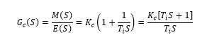 (9)
(9)
- The gain Kc of the controller is calculated using the modulus condition given by Equation (10)
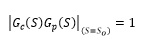 (10)
(10)
- The discrete equivalent D(z) of the estimated continuous controller Gc(S) can be obtained using the bilinear transformation or the Tustin method [26] given by Equation (11):
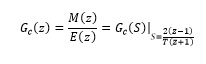 (11)
(11)
Where (T) is the sampling period.
3.2 PI Servo type controller design with integrator
Figure 2 shows a full-order observer state feedback control system in which an additional integrator is used to properly stabilize the system and improve its accuracy [27, 28].
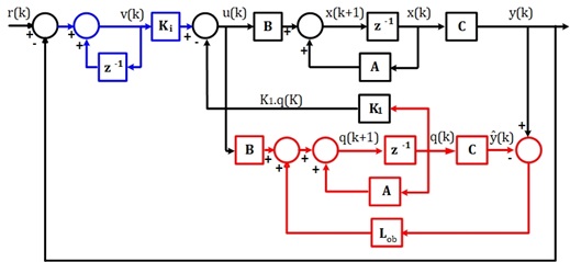
Figure 2. Servo system with integrator
The control system consists of a full-order state observer which estimates the non-measurables state variables and an integrator whose purpose is to reduce the SteadyState error to zero. The addition of the integrator increases the order of the system by one, therefore, it is necessary to work with extended matrices (12) and (13).
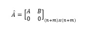 (12)
(12)
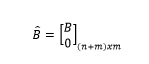 (13)
(13)
Calculation of the matrices K_1 and K_i in the Equations (14) and (15)
 (14)
(14)
 (15)
(15)
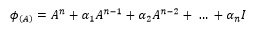
Where ϕ_((A ̂ ) ) is given by Equation (16)
 (16)
(16)
Where α_1,〖α_2〗_,….α_n are the coefficients of the desired characteristic equation for the feedback gain matrix with the integrator.
The Observer Gain Matrix, L_ob is estimated using the Ackerman formula [29] given by Equation (17)
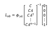 (17)
(17)
Where ϕ_((A) ) is given by Equation (18)
 (18)
(18)
3.3 MPPT Algorithm perturb and observe (P&O)
The P&O algorithm involves making small periodic perturbations by increasing or decreasing the output voltage of the photovoltaic system. If the perturbation results in a higher power output, the next perturbation continues in the same direction; otherwise, the direction of the perturbation is changed. Once the maximum power point is reached, the algorithm utilizes its characteristics to maintain the operating point oscillating around that point [30]. The flow chart of the P&O method is shown in Figure 3 where the output provides a v_pv reference to the controller.

Figure 3. flow chart of P&O method.
4. RESULTS
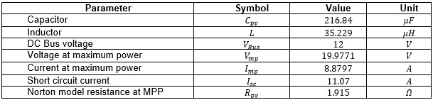
Considering the information from Table 1, Figure 3 describe the proposed system to be evaluated in its performance, for the two control strategies detailed in the section 3. Replacing the values of Table 1 in Equations (6) and (7), the state-space model is given by (19) and (20).
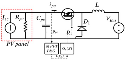
Figure 3.Proposed system to be evaluated with LRM and Servo type controller.
Table 1. Operating point values.
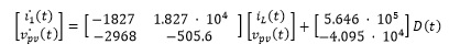 (19)
(19)
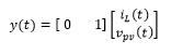 (20)
(20)
The discrete-time system with T = 13.4μs is (21) and (22)
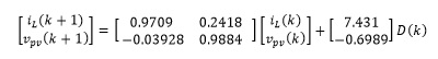 (21)
(21)
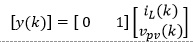 (22)
(22)
The transfer function which relates the panel voltage to the duty cycle D(t) is (23)
 (23)
(23)
For the design of the controllers, the poles are set to obtain a closed-loop settling time equal to 75% of corresponding to the model of the original open-loop system and a damping coefficient of 0.7 is assumed. The controller obtained with the root locus method gives as a result the Equation (24)
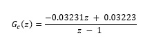 (24)
(24)
Likewise, for the servo controller with integrator, the following matrices for the state feedback are obtained (25) and (26)
 (25)
(25)
 (26)
(26)
To calculate the observer matrix, a settling time equal to 60% of corresponding open-loop model of the original system and a damping coefficient of 0.7 is assumed as shown in Equation (27)
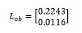 (27)
(27)
Once the control strategies are designed, the next step corresponds to build the PV system, the P&O algorithm, and the control strategies in the Simulink environment as detailed in Figure 4.
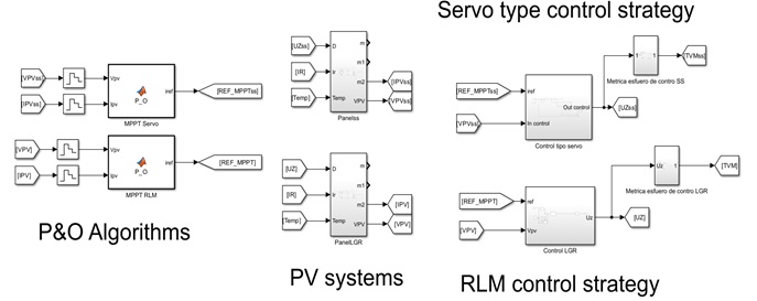
Figure 4. Proposed system in Simulink.
As shown in Figure 4, four labels show each designed system, the first one corresponds to the P&O algorithm written in C language. Next, the PV system is created as detailed in Figure 5.

Figure 5. PV system linked to a DC bus interfaced by a buck converter.
In Figure 5, a PV array block is parameterized with the commercial values of the PV panel reported in [31]. Then, the parameters of Table 1 are provided to the components. Likewise, in Figure 6 the servo type controller con-figuration is provided.
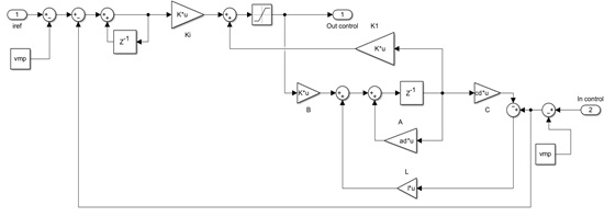
Figure 6. Servo type controller configuration.
Finally, in Figure 7 the RLM controller configuration is detailed where gain “L”, “K1” and “Ki” correspond to the Equations (25), (26) and (27), respectively.
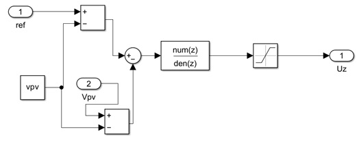
Figure 7. RLM controller configuration.
Moreover, in Figure 7 depicts the transfer function obtained by Equation (24) to locate the desired poles given the designer criteria.
In the simulation of the incident radiation signal on the photovoltaic panel, an up-and-down ramp was used in the solar radiation profile, because physically the variation of solar radiation does not follow the behavior of a step signal.
To test the designed controllers, it is proposed the next conditions; first, the irradiation begins at 800 W/m2 for 0.4 seconds, then a ramp-type perturbation to reach 1000 W/m2 is performed for the next 0.4 seconds and then, a downward ramp until 700 W/m2 until 1.4 seconds. In Figure 8, the ideal power generated by the panel and the actual power obtained with each of the designed controllers are shown. At the beginning of the first ramp, there is a noticeable difference between the ideal trajectory and the one obtained with both controllers. This is because the MPPT algorithm is in the process of adjusting the reference. Once the reference is reached, the actual power aligns with the reference generated by the MPPT. An analysis of the response indicates that the MPPT algorithm and the designed controllers allow for proper tracking of the maximum ideal power in response to changes in the irradiation value. Figure 9 corresponds to the response of tracking the maximum power voltage reference delivered by the MPPT algorithm for each of the controllers. In both cases, the tracking of the reference is acceptable, with a smooth response and barely noticeable oscillations. It is evident that the Servo type controller with integrator exhibits a shorter settling time compared to the RLM. Figure 10 represents the behavior of the control law for the two regulators. It can be observed that both regulators exhibit a smooth behavior without saturation or significant overshoots. The output of both controllers remains around similar values, with a duty cycle of approximately 70%, indicating a low variability control effort.

Figure 8. Comparison of power extraction between the two control strategies
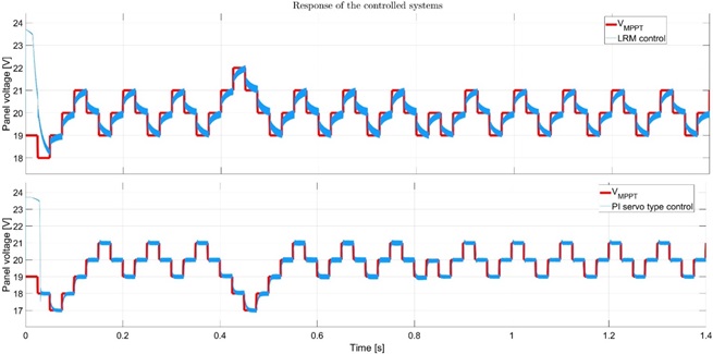
Figure 9. Response of controlled systems
In Table 2, the obtained values of performance indices used to compare the performance of the controllers are presented. The criteria used include the Integral of the Absolute Error for reference tracking (IAE), for panel voltage and output power; also, the Effort of the Manipulated Variable (EMV) to evaluate the duty cycle performance. Based on the information from Table 2, it can be noted for the proposed system configuration, the servo PI controller presents a better performance from the 〖IAE〗_Voltage and EMV metrics, indicating a more accurate operation and soft switching performance in the PV system; nevertheless, the RLM control reports a lower 〖IAE〗_Power which indicates that such a strategy performs better to extract the maximum available power but increasing the EMV; i.e., a more aggressive switching.
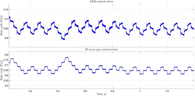
Figure 10. The response of the control law
Table 2.Controller performance index for extracted power and panel voltage.

The simulation of the PV system performance was conducted using Matlab/Simulink® software, employing a P&O algorithm and two control strategies: a servo controller with an integrator and a PI controller based on root locus techniques. This proyect provides a valuable tool for simulating and implementing MPPT and control strategies that best suit the solar panel's charge control system. Analyzing the solar panel's behavior is highly useful for sizing photovoltaic systems. Through these simulations, it becomes possible to predict, with greater accuracy, the amount of energy that can be generated in response to changes in irradiance.
Two control strategies were designed: PI control using RLM and a Servo type system with integrator. Both controllers follow the voltage reference imposed by the MPPT algorithm. The responses do not exhibit oscillations other than those caused by the switching of the MOSFETs, nor do they show overshoot. In terms of settling time, it is observed that the servo-type algorithm with integrator has a faster response speed. Regarding control effort, both controllers behave similarly, presenting a PWM with a duty cycle of approximately 70%, exhibiting smooth action, and no saturation in the final control element. Commercial PV systems coupled with a power converter propose a unique system to be controlled. Thus, it is necessary to design one that satisfies not only the controller criteria, but also certain efficiency metrics such as IAE and EVM. Thus, it would be possible to find among the different applicable controllers, the one that best fits the system.
The authors appreciate the support received from the University Institution of Envigado, the Faculty of Engineering and the Research Group on Sustainable and Intelligent Emerging Technologies (GITESI) through the research Project: Study to determine the efficiency of classical MPPT algorithms to deliver the energy of a solar panel to a battery considering partial shading, irradiation and temperature changes.
[1] Dubey, S., Sarvaiya, J. N., & Seshadri, B. (2013). Temperature dependent photovoltaic (PV) efficiency and its effect on PV production in the world–a review. Energy Procedia, 33, 311–321.
[2] Zúniga-Ventura, Y. A. (2014). Control del punto de máxima potencia en paneles solares bajo variaciones de radiación y temperatura (Master's thesis).
[3]SİHAM, A., Bechouat, M., Sedraoui, M., Kahla, S., & Amieur, T. (2023). Synthesis of Voltage PID Controller to Improve INC-MPPT Algorithm for Cascade Regulation of KC200GT Panel-Based Solar System. Avrupa Bilim ve Teknoloji Dergisi. European Journal of Science and Technology Special Issue 47, pp. 73-78, January 2023 Copyright © 2023 EJOSAT.
[4] Yadav, H. K., & Mehar, V. (2022) Design and Analysis of PV System with P&O Method MPPT Technique and PID Controller algorithms, 10, 11.
[5] Woodhouse, M., Jones-Albertus, R., Feldman, D., Fu, R., Horowitz, K., Chung, D., Kurtz, S. (2016). On the path to sunshot. the role of advancements in solar photovoltaic efficiency, reliability, and costs (Tech. Rep.). National Renewable Energy Lab. (NREL), Golden, CO (United States).
[6] Khamooshi, M., Salati, H., Egelioglu, F., Hooshyar Faghiri, A., Tarabishi, J., Babadi,S., et al. (2014). A review of solar photovoltaic concentrators. International Journal of Photoenergy, 2014.
[7] Benhadouga, S., Belkaid, A., Colak, I., Meddad, M., & Eddiai, A. (2021, September). Experimental Validation of The Sliding Mode Controller to Improve The Efficiency of The MPPT Solar System. In 2021 10th International Conference on Renewable Energy Research and Application (ICRERA) (pp. 333-337). IEEE.
[8] Cuellar, J. A. (2019) Diseño de un controlador para el seguimiento del punto de máxima potencia (MPPT) en paneles solares. Tesis de maestría. Universidad Santo Tomás. Maestría en Ingeniería Electrónica. Facultad de Ingeniería Electrónica. Bogotá, Colombia
[9] Attia, H. (2019). High performance PV system based on artificial neural network MPPT with PI controller for direct current water pump applications. International Journal of Power Electronics and Drive Systems, 10(3), 1329-1338
[10] Tapia Palma, J. C. (2023). Diseño y simulación de un Sistema de Tracking basado en redes neuronales para mantener la máxima eficiencia de paneles solares (Master's thesis, Ecuador: Latacunga: Universidad Técnica de Cotopaxi, (UTC)).
[11] Martín, M., Marjorie, N., & Jesús, R. F. (2023). Diseño de un Controlador Adaptativo por Modelo de Referencia Usando la Regla del MIT Aplicado a un Convertidor DC-DC Reductor de Voltaje. Revista Politécnica, 51(1), 19-28.
[12] Tyagi, V., Rahim, N. A., Rahim, N., Jeyraj, A., & Selvaraj, L. (2013). Progress in solar PV technology: Research and achievement. Renewable and sustainable energy reviews, 20, 443–461.
[13] Touil, S. A., Boudjerda, N., Boubakir, A., & Drissi, K. E. K. (2019). Closed loop discontinuous pulse width modulation control used in inverter grid-connected photovoltaic system for reduced switching losses. Rev. Roum. Sci. Techn.–Électrotechn. et Énerg, 64(4), 357-363.
[14] Cuellar, J. A. , Pinzón, C. A. , & García, E. F. (2021). Diseño de un convertidor boost cuadrático controlado mediante el algoritmo de perturbar y observar. In Desarrollo e Innovación en Ingeniería (pp. 90-100). Instituto Antioqueño de Investigación (IAI).
[15] S¸ahin, M. E., & Okumu¸s, H. ˙I. (2018). Comparison of different controllers and stability analysis for photovoltaic powered buck-boost dc-dc converter. Electric Power Components and Systems, 46 (2), 149–161.
[16] Raghavendra, K. V. G., Zeb, K., Muthusamy, A., Krishna, T., Kumar, S. V. P., Kim, D.-H., Kim, H.-J. (2019). A comprehensive review of dc–dc converter topologies and modulation strategies with recent ad-vances in solar photovoltaic systems. Electronics, 9 (1), 31.
[17] Radhika, S., & Margaret, V. (2021). A review on dc-dc converters with photovoltaic system in dc micro grid. In Journal of physics: Conference series (Vol. 1804, p. 012155).
[18] Pesantez, J. P., Ríos Villacorta, A., & Redrován, J. G. (2021). Integración de Sistemas Solares Fotovoltaicos en el Sector Camaronero Intensivo y Extensivo del Ecuador: Caso de Estudio en la Provincia de El Oro. Revista Politécnica, 47(2), 7-16.
[19] Carrión-Chamba, W., Murillo-Torres, W., & Montero-Izquierdo, A. (2022). Una revisión de los últimos avances de los colectores solares térmicos aplicados en la industria. Ingenius. Revista de Ciencia y Tecnología, (27), 59-73.
[20] Corti, F., Laudani, A., Lozito, G. M., & Reatti, A. (2020). Computationally efficient modeling of dc-dc converters for PV applications. Energies, 13 (19), 5100.
[21] Ishaque, K., Salam, Z., & Taheri, H. (2011). Simple, fast and accurate two-diode model for photovoltaic modules. Solar energy materials and solar cells, 95 (2), 586–594.
[22] Herrera-Jaramillo, D. A., Henao-Bravo, E. E., González Montoya, D., Ramos-Paja, C. A., & Saavedra-Montes, A. J. (2021). Control-oriented model of photovoltaic systems based on a dual active bridge con-verter. Sustainability, 13 (14), 7689.
[23] Nayak, B., Mohapatra, A., & Mohanty, K. B. (2017). Selection criteria of dc-dc converter and control variable for MPPT of PV system utilized in heating and cooking applications. Cogent Engineering, 4(1), 1363357. Electrical & Electronic Engineering | Research Article
[24] Nedumgatt, J. J., Jayakrishnan, K., Umashankar, S., Vijayakumar, D., & Kothari, D.(2011). Perturb and observe MPPT algorithm for solar PV systems-modeling and simulation. In 2011 annual IEEE India confer-ence (pp. 1–6).
[25] Siddiqui, M. A., Anwar, N., & Laskar, S. H. (2019, March). A simple tuning approach for PID controller based on direct synthesis and rootlocus. In 2019 3rd International Conference on Computing Methodologies and Communication (ICCMC) (pp. 466-470). IEEE.
[26] Vargas-Tamani, B. (2009). Aproximación digital de controladores sintonizados y comparación con con-troladores continuos y digitales diseñados. Electrónica UNMSM, 2.
[27] Palacios, A. (2017). Controlador con observador de estados de orden completo para un motor de DC mediante dspace., 7 (1).
[28] García Jaimes, L. E, G. M. A (2010). Controlador tipo servo con observador de orden completo y con-trolador según Ciancone Marlín para un sistema de flujo. 6 (10), 34-43.
[29] Martinez Rodriguez, J. L., & Morales Rodriguez, J. (2016). Control aplicado con variables de estado. Ediciones Paraninfo, SA.
[30] Henríquez Seguel, F. N. (2023). Implementación de un MPPT (Maximum Power Point Tracking) para panel fotovoltaico usando PLC Fatek FBs–20MCR. Universidad de Concepción Facultad de Ingeniería Departamento de Ingeniería Eléctrica.
[31] Restarsolar, Panel solar 210 watts monocristalino Restarsolar https://www.solartex.co/tienda/producto/panel-solar-210-watts-monocristalino-restarsolar/, (accessed Nov. 7, 2023)