1. INTRODUCTION
Control schemes based on reactive architectures have become stronger in the mobile robotics field [1] during the last decade. Such architectures offer advantages to robotic systems by allowing them to perform control actions and by keeping an almost direct relation between sensors and actuators, unlike the classic or traditional model, which uses a deliberative architecture constituted by three levels: Data acquisition (lowest level), Navigation software (intermediate level) and Planner (upper level) [2], which take more time in conducting a control action.
In the first mentioned architecture, complex navigation tasks are separated into a series of modules called behaviors, which are designed so that they perform a specific task [3]. These behaviors are executed in parallel and there is no need of incorporating complex synchronization [4]. By contrast, in the second architecture mentioned, the data sensed by the robot must go through both the first and the second levels to reach the planner, think about the systems needs and generate a control action. This architecture has several disadvantages, such as the use of complex controllers, and takes long periods of time in making the control decision, it being crucial for a robot system on wheels [4,5].
The first architecture based on the reactive paradigm was proposed by Brooks [6], which is constituted as a competitive mechanism based on priorities, where only the behavior showing the greatest preference can be applied to the robot. Although Brooks proposal sometimes presents inaccuracy in the robot's movements [5], four advantages can be highlighted: first, there is reaction in real time due to the parallel work of the behaviors; second, In the performance, it have advantages in unknown environments due to the fact that each behavior can acquire data on-line and make a decision immediately; third, the behaviors can be simple, with great flexibility; fourth, it is robust enough [2,7].
Reactive architectures present a problem that has been permanently worked on behaviors design. This focuses on how the robot must interact when facing a situation [8].
An artificial intelligence technique that has been widely used to fix the problems of behavior design is fuzzy logic, which combines the strength of fuzzy control with the perception-action typical of reactive architectures [9]. Several examples of the implementation of behaviors designed with fuzzy logic in simulation systems for mobile robots as well as in prototypes can be found in [10, 14].
This paper presents the design of three behaviors obstacle avoidance, right wall following, and left wall following based on fuzzy logic. The designed controls are all constituted by the P controller characteristics for obstacle avoidance and PD for wall following, all controls initially are tested separately to check its performance. Later, the integration of behaviors by subsumption architecture. Finally, the results and conclusions are shown.
This article is aimed at presenting the design of behavior-based fuzzy controllers, a simple form of how-to co-ordinate them and in a general way to demonstrate that this artificial intelligence technique is in force and fully functional for control schemes for small and medium-sized robots.
2. MATERIALS AND METHOD
Behaviors in mobile robots
In the field of mobile robotics, the techniques of intelligent control have become a mechanism by which systems of control with greater strength can be designed, specially behavior-based control for mobile robots, which has been consolidated as a highly used technique, and has gained great popularity inside the scientific community that works in the field of mobile robotics [8,15]. According to Arkin, a behavior is defined as: “The reaction to a stimulus” [16, p. 66].
Behaviors are then established as the reactions that robot can take in a certain situation according to the stimuli that the navigation environment presents (walls, objects, hallways, corners, etc.). There are some behaviors that safeguard the integrity of the robot, for instance, obstacle avoidance [11,14] and followings of walls [7,13]. When used together these behaviors provide the robot with enough autonomy to carry out safe navigation tasks.
Design of fuzzy controllers
Layout of the robot's measurement sensors. The hierarchic architecture of behavior-based fuzzy control was designed from detection zones for which the ultrasound sensors used in the robot system were enabled, as it is shown in figure 1.
The robot presents two main frontal zones the right and left front zones, two groups of two sensors for each one was adopted, while the other zones used a single sensor.
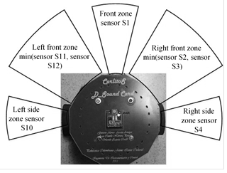
Fig.1. Scheme of sensorial layout for detection
Obstacle avoidance behavior. The design of this behavior uses the layouts of sensors of the right and left front zones and the front zone as it is shown in figure 1. Each zone used a detection threshold or set-point as follows: 75cm for the side front zones and 120cm for the front zone. The detection thresholds used for this behavior were experimentally tested.
|
|
(1) |
|
|
(2) |
|
|
(3) |
Each of the three abovementioned variables is divided as follows: {eS1_ (Nt, Pt); ef (L, R) _ (Nt; Pt)}; where e: error; fe (L, R): left and right frontal error; Nt: Negative; and Pt: Positive. The graphic representation of these sets can be observed below in figure 3. The control scheme is presented in figure 2. It illustrates the process the information measured by the sensors and the transformation and processes needed must go through, so that they are later interpreted as control signals that modify the states of the motors and are able to avoid the obstacle.
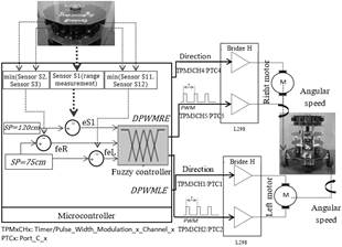
Fig.2. Control Scheme - Obstacle avoidance
The behavior works with the error variables for all the frontal zones, which is why it constitutes itself as a pure P controller. The block of the fuzzy controller is presented by a mamdani inference system that have significant advantages like Intuitive, well-suited to human input, more interpretable rule base and widespread acceptance. Obstacle avoidance and left and right wall following controllers are based in mamdani inference system. Obstacle avoidance was designed with Three fuzzy input variables, which represent the front error variables towards objects, and two fuzzy output variables, which affect the modification of the motor revolutions.
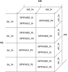
Fig.3. Table FAM of the associative to the obstacle avoidance
The inference mechanism appears in figure 3, where the controller's rules considered by the design are recorded in tabular form. for the first rule, the three variables present a negative state (Nt), which indicates there is no frontal object. That implies for the output variables to be in state zero (Zr), which makes the motor revolutions not to be modified for that particular situation; this is considered as roaming of the robot until it finds an object that prevents its navigation.
Figure 4 shows the membership functions of inputs were defined like trapezoidal membership functions and the output were defined like polygonal membership functions because these shapes are more simple and are computationally lighter. For this fuzzy controller the inputs (eS1, feL, feR) have the same form, just as the output variables (DPWMLE, DPWMRE) also share the same form in turn. The decision that both, input variables and the variables have the same form, is intended to make the control in its response as linear as possible. These design considerations were adopted for the other controllers.
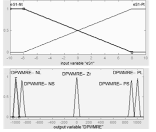
Fig.4. Membership function - obstacle avoidance
Output variables called DPWMRE and DPWMLE (Delta of PWM Right and Left Evasion) were each decomposed into 5 fuzzy sets of the singleton type {DPWME (R,L) _ (NL, NS, Zr, PS, PL)} where NL: Negative Large, Negative Small; Zr: Zero; PP: Positive Small; and PL: Positive Large. Defuzzification for this behavior and wall following were made by using the centroid method, in which the fuzzy output becomes a real control value. The preliminary results of each controller are presented once the design is presented.
Preliminary Results of obstacle avoidance. For the navigation experimental test, a static scenario where objects were positioned to the right and left of the robot was proposed, as it is shown in figure 5.
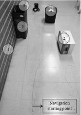
Fig.5. Navigation scenario proposed for obstacle avoidance test
Figures 6 present the data collected from the figure 5 obstacle avoidance tests.
a)

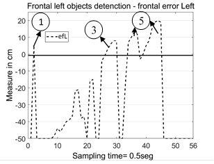
b)
Fig.6. a) Frontal left objects detection, b) Frontal right objects detection
In figure 6-a) labels 1 and 5 show the detection of the left wall; whereas label 3 describes the detection of the waste container on the left. Figure 6-b), labels 2 and 4 represent the other two objects detected on the right. It is inferred that if an object passes the detection threshold or set point, the error of the input variables is positive, which suggests the robot the need to avoid the obstacles.
Right wall following. This controller works according to the variables of the error and the derivative of the error of the S4 sensor, which constitutes it as a PD controller. The set-point of the controller was 60cm towards walls on the right. Variables are expressed as follows:
|
|
(4) |
|
|
(5) |
By analyzing the variable of the error and the derivative of the error, information about the proximity or distance of the robot towards the right wall can be obtained, and it can be known if the robot is moving closer, away or parallel to the wall. This information is of utmost importance because the conditions for the output variables of the right motor were proposed based on the conditions previously explained. Table 1 presents the rules for the states of the error variable and the derivative of the error.
Table 1. Table FAM-right wall following.
|
|
deS4_Nt |
deS4_Zr |
deS4_Pt |
|
eS4_Nt |
DPWMRW_NS |
DPWMRW_NL |
DPWMRW_NS |
|
eS4_Zr |
DPWMRW_NS |
DPWMRW_ZR |
DPWMRW_PS |
|
eS4_Pt |
DPWMRW_PS |
DPWMRW_PL |
DPWMRW_PS |
Input variables of this controller are expressed as three sets for each variable {eS4_ (Nt, Zr, Pt) and deS4_ (Nt, Zr, Pt)} where e: error; de: derivative; Nt: Negative; Zr: Zero; Pt: Positive. This behavior was designed to control the right motor only. Thus the output variable of this control is a single one called DPWMRW (Delta de PWM Right Wall), which was divided in five output sets of the singleton type DPWMRW (NG, NS, Zr, PS, PL), where NL: Negative Large, Negative Small; Zr: Zero; PP: Positive Small; and PL: Positive Large. Figure 7 shown the Control Scheme of the controller and figure 8 present the sets of fuzzy membership functions of input(eS4, deS4) and output(DPWMRW).
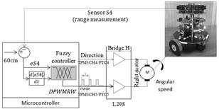
Fig.7. Scheme of control - Right wall following
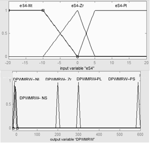
Fig.8. Membership function - Right wall following.
Preliminary Right wall following results. Figure 9 presents the collected data from one of the navigation tests carried out for the designed controller.
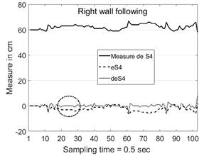
Fig.9. Telemetry - Right wall following
In the figure 9 can be observed that the robot comes near and oscillates close to the set-point of 60 cm, which means that the robot navigates according to the design and it reaches goal for this behavior. In the bottom lines, it can be seen how the error and the derivative of the error move. For the dotted circle in figure 15, a negative error can be observed, which indicates that the robot is far from the wall and above the set-point. It is also observed that the derivative is zero, which indicates that the robot is parallel to the wall at that moment. It is expected that the robot looks for the set-point. Later, time after the previous analysis, it is observed that the robot approaches the wall trying to correct the error.
Left wall following. This design is this behavior is almost the same process seen in the right wall following behavior but using sensor 10 (sensor is located to the robot's left side of the robot), the error variable(eS10) and the derivative of the error associated to sensor(deS10). The following equations represents these variables.
|
|
(6) |
|
|
(7) |
The scheme of control - Left wall following is the same schema using in figure 7, but the communication channels are different, and the dynamic of the left motor was considered for the design.
Nevertheless, it must be considered that although the sensors and motors have the same manufacturing standards, they can have minimal differences and behave differently before the same stimulus.
Table 2 display the design for this controller and Figure 10 shown the fuzzy sets made for the error variables and the derivative of the error that they are totally different when compared to the sets of the previous behavior.
![]() Table
2. Table FAM-left wall following
Table
2. Table FAM-left wall following
|
|
deS10_Nt |
deS10_Zr |
deS10_Pt |
|
eS10_Nt |
DPWMLW_NS |
DPWMLW_NL |
DPWMLW_NS |
|
eS10_Zr |
DPWMLW_NS |
DPWMLW_ZR |
DPWMLW_PS |
|
eS10_Pt |
DPWMLW_PS |
DPWMLW_PL |
DPWMLW_PS |
For the input and output variables, {eS10_ (Nt, Zr, Pt) and deS10_ (Nt, Zr, Pt)} e: error; de: derivative of the error; Nt: Negative; Zr: Zero; Pt: Positive. The output variable DPWMLW (Delta of PWM Right Wall) was also divided into five output sets of the singleton type DPWMLW_ (NL, NS, Zr, PS, PL).
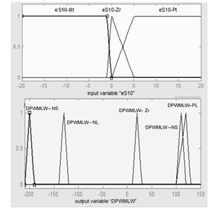
Fig.10. Membership function - Left wall following
Preliminary Left wall following results. Figure 11 shows the telemetry data of a navigation test of left wall following.
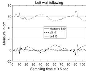
Figure 11. Telemetry - Left wall following
The results for this wall following are more oscillatory than for the previous one. This confirms that even though the behaviors of wall following were designed with the very same procedure, they show totally different characteristics.
3. BEHAVIORS INTEGRATION METHODOLOGY
The integration of the behaviors was carried out by using an subsumption architecture, which subsumes the least priority behavior. The priority of the behaviors and the abovementioned architecture are shown in figure 12.
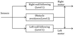
Fig.12. Subsumption for robot CARLITOS
Figure 12 presents that obstacle avoidance has greater priority (level 2) than the following of walls (level 1), which are at the same level. Figure 13 presents the complete control architecture where is defined the whole process, sensor data reading, compare readings against set-point, subsumption architecture that allows launch the correct behavior by the priority assessment and finally the robot movement.
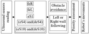
Fig.13. Control architecture
Figure 14 presents the mechanism of priority of the behaviors, the activation conditions of the behaviors can be seen, according to the priority and the reading of sensors.
The right or left wall following behavior have the same priority mechanism, but each behavior works with its sensor and associating these readings with left or right obstacles detections “minL and minR” it lets to launch the correct behavior control. minL and minR are variables that allows calculate the following sensory inference where minL is equal to minimum distance between sensors S11 and S12 and minR is equal to minimum distance between sensors S2 and S3.
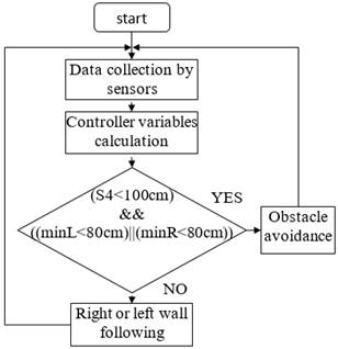
Fig.14. Priority mechanism
4. Results and Discussion
Figure 15 present the two experiments to check the previous design of subsumption architecture using the behaviors controllers.
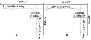
Fig.15. Tests Scenario - Architecture of subsumption
In the demarcated zones the robot activated the behavior according to the control architecture and sensory inference. The activation of right wall following and obstacle avoidance can be seen in figure 15-a. and figure 15-b shows the activation of left wall following and obstacle avoidance.
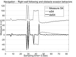
Fig.16. Right wall following and obstacle avoidance.
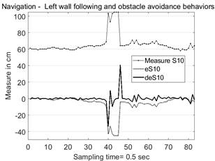
Fig.17. Left wall following and obstacle avoidance.
Figure 16 and 17 presents that the robot initially described a right or left wall following, reaching closest to the set-point. Later, some peaks are observed, which describe wrong readings that are associated to the specular reflection or grown data of the ultrasound sensor. In the internal routines of the algorithm this data was filter. From seconds 35 to 45, a corner was detected to the left or right, which is understood as an obstacle, and therefore, avoided. Finally, after second 47, it can be observed for both tests how the robot avoids the corners and gets out of them searching for the set-point in order to keep the wall following. Figure 17 shows more oscillations in the end of experiment, but the same objective is kept, reach the wall.
5. CONCLUSIONS
For the designed control system, it was essential to keep a strategy that allowed to make instant adjustments to the re-design tasks of the behaviors as well as to the global control system. The appropriation of the experts' knowledge was also key to be materialized in the design, as well as the knowledge of the robot system to the maximum.
The subsumption architecture integrated the designed behaviors effectively, which resulted in the description of suitable trajectories for the robotic system.
The implementation of logics and the contributions of the design expert also played an essential role. Fuzzy logic helped in a strategic, precise and simple way with the materialization of the ideas that were expressed in the behaviors. It can be affirmed that fuzzy logic constituted as a robust and flexible strategy for the design of behavior-based controllers for mobile robots.
The behavior set was satisfactorily designed, meeting the design guidelines initially defined. These behaviors had good performance keeping the set-point, which make them suitable to offer the robot safe navigation Although the behaviors were designed carefully, there is still the possibility to continue making efforts on tuning to improve them.
in this article presents just one of many experimentation that led to satisfactory results, creating a strong knowledge base regarding the behavior design of wall following and obstacle avoidance and in general, this process of design allowed to consolidate experiences and knowhow that could be useful in further implementations of behaviors-based fuzzy controllers .
6. ReferencES
[1] M. I. Fadholi, Suhartono, P. S. Sasongko, y
Sutikno, «Autonomous Pole Balancing Design In Quadcopter Using
Behaviour-Based Intelligent Fuzzy Control», en 2018 2nd
International Conference on Informatics and Computational
Sciences (ICICoS), 2018, pp. 1-6.
[2] J. C.
Vega Oliver y P. F. Huamaní Navarrete, «Fuzzy control to
simulate 4 autonomous navigation behaviors in a
differential-drive mobile robot», en 2017 IEEE International
Conference on Aerospace and Signals (INCAS), 2017, pp. 1-4.
[3] K.-T. Song and J.-Y. Lin, “Behavior Fusion of
Robot Navigation Using a Fuzzy Neural Network,” in IEEE
InternationalConference on Systems, Man and Cybernetics, 2006.
SMC ’06, 2006, vol. 6, pp. 4910-4915.
[4] P.
Gyawali y P. K. Agarwal, «Fuzzy Behaviour Based Mobile Robot
Navigation in Static Environment», en 2018 IEEE Recent
Advances in Intelligent Computational Systems (RAICS),
2018, pp. 190-194.