1. INTRODUCTION
The excessive demand of energy is leading into research of new distributed energy systems such as smart grids, which use renewable energy resources such as photovoltaic solar panels, wind turbines and fuel cells to supply electric energy together with the main electric grid to feed the loads [5],[12]. They also have energy storage systems and Advanced Metering Infrastructure systems (AMI), which are responsible of the power measurement, control and the communication network to manage and supervise the status of the grid from a control room [1],[13],[15],[16].
A smart grid is an automated electric distribution system composed by renewable energy resource, an advanced metering infrastructure system and a SCADA system. The SCADA and the advanced metering systems play along a key role in order to control and measure the energy demand of an electric grid [2]. The low power generators composed by renewable energy resources, and the measuring and control devices allow redundancy feeding systems, automatic detection and localization of failures, and self-healing, in order to improve the electric energy distribution services. A smart grid can also help to reduce the highest peak of energy consumption during a day by using intelligent meters capable of measuring the demand of energy. By knowing the dynamic of the energy demand consumption during a day, the users can know the intervals of time in which the energy has a lower price. With this, which is called Demand Response, users will decrease their consumption during rush hours and increase their consumption during the off-peak time, reducing the highest peak of energy consumption and reducing the effort of the central generators [15].
Commercial RMU devices are capable of measuring current, detecting faults and protecting the elements of the grid by using breakers in case of fault. They can also be remote controlled in order to manage and reconfigure the electric grid manually. Commercial RMU devices are not capable of detecting electric faults and automatically reconfigure the grid in order to make self-healing to overcome the fault by managing automatically the flow of energy in the grid. Is necessary to design a RMU capable of monitoring, controlling and reconfiguring automatically the electric grid in order to protect and overcome faults to guarantee energy supply to the critical loads. By having a wireless mesh network, all the RMU devices that are connected in the grid can communicate with each other in order to manage the operations of the grid automatically.
This article presents the design of a RMU device that was installed in the nodes of a 12V AC scaled smart grid to make power measurement and automatic control in order to manage and supervise the status of the grid with a SCADA system [2]. The RMU device was designed to manage automatically the grid, being capable of measuring power, fault detection and automatic reconfiguration of the grid in order to overcome faults in a scaled electric grid of 12V AC. The device measures RMS voltage, RMS current, frequency, reactive power, power factor and temperature, and then sends all the information to a computer that plays the role of a control room where the supervisory system is being held [6]. This device is also able to receive command messages from the computer to perform control actions like connecting/disconnecting the grid to manage the flow of energy between the nodes of the smart grid. [3]
This article is divided as follows: Section 2 explains the methodology used in the design of the RMU device. Section III shows the operation results of the RMU after testing it in a controlled environment inside a scaled smart grid. Section IV mentions the research project that financed the present work. Section V shows the conclusions of the work.
2. METHODOLOGY
The RMU device was designed in order to work in a 12V scaled smart grid. So, after the topology of the smart grid was designed, the first step was to identify the main characteristics that the device should have in order to allow the management of the smart grid. It was decided that the device should measure the electric variables of the grid, send wireless information of the status of the grid, detect any voltage or current failure, be capable of connecting or disconnecting the grid in order to make self-healing, and have a specific size in order to install multiple devices inside the smart grid.
After the characteristics of the device were decided, the electronic design began. To make the design of the device it was used a software tool in order to make simulations. Then, it was developed a first prototype using a protoboard in order to make some tests using the scaled electric grid and finally it was designed the PCB.
The methodology is divided as follows: Subsection II.I shows the general structure of the RMU. Subsection II.II explains the basic operations of the RMU. Subsection II.III shows the principal characteristics and specifications of the RMU. Subsection II.VI explains the communication and monitoring system.
2.1. GENERAL STRUCTURE OF THE RMU DEVICE
The RMU is composed by one main module which is responsible of measuring the electric variables in the grid and two secondary modules that connect or disconnect the grid in order to allow the flow of energy through the grid or to isolate a specific part of the smart grid. A secondary module is composed by a microcontroller, a voltage conditioning circuit, a current conditioning circuit, a relay and two indicator LEDs. The main module is composed by a microcontroller, a voltage conditioning circuit, a current conditioning circuit, a relay, a power sensor, an XBee module and four indicator LEDs that show if the relay is closed, if there is any voltage failure, if there is any current failure or if the device is operating in a special way.
Figure 1 shows a general block diagram of the complete RMU device which is composed by one main module and two secondary modules. Using multiple RMU devices in an electric grid allows the secondary modules to control the flow of energy through the grid, and to detect and locate a failure by knowing if the failure has occurred before the secondary module A or after the secondary module B. The main module allows the connection between the load and the grid.
This RMU device can be used in the smart grid to have a redundancy feeding system configuration to guarantee availability of energy to a sensitive load by allowing flow of energy coming from both sides (see figure 1). Passing through the secondary module “A” to the load or passing through the secondary module “B” to the load [9]. In case of failure in one of the grids that supplies energy that passes through one of the secondary modules, for example secondary module “A”, the RMU can isolate the damaged grid by disconnecting the secondary module “A”. Then the secondary module “B” is connected to allow flow of energy coming from an auxiliary substation to ensure power on the sensitive load [8].
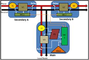
Figure 1. Complete Block diagram of the RMU (Source: own elaboration)
Figure 2 shows the block diagram of the main module. The electric grid passes through the conditioning circuits to obtain samples for the power sensor in order to measure voltage and current. In case of a power failure the relay opens to protect the load [11]. All the measurements from the power sensor are sent to the microcontroller using SPI communication and then the microcontroller sends all the information of the measured variables and the status of each RMU module to a computer using an XBee module to get wireless communication [7].
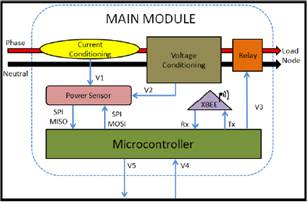
Figure 2. Block diagram of the Main Module (Source: own elaboration)
Figure 3 shows the block diagram of the secondary module, where the electric grid passes through the conditioning circuits and the relay, in order to achieve voltage and current samples to measure and disconnect the grid in case of detecting a voltage or current value out of the normal operation range.
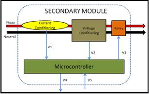
Figure 3. Block diagram of the Secondary Module (Source: own elaboration)
2.2. OPERATION MODE OF THE RMU MODULES
The RMU can operate in four different configurations:
· The Main Module connected to the SA (Secondary Module A).
· The Main Module connected to the SB (Secondary Module B).
· The Main Module connected to SA and SB.
· The Main Module connected alone without any Secondary Module.
These four configurations of the RMU can be used in the smart grid depending on the applications and the necessities. It is always necessary to use a Main Module because this module is the responsible of the wireless communication by sending information and receiving all the commands [9].
Main Module:
The Main Module of the RMU can operate by itself and can do the following tasks:
· Measure the electric variables of the grid: voltage, current, frequency, reactive power, power factor and temperature.
· Detect voltage or current failures and disconnect automatically.
· Send information of the measurement and the status of each module to a computer using an XBee module.
· Receive commands from a computer.
The Main Module has been configured to operate in a 12 V AC electric grid, in which a voltage failure has been defined if the voltage level is out of the range between 10.8 – 13.2 V. This range has been defined based on the Colombian electric grid standards where a voltage drop/rise is assumed as a failure if its value changes more than +/-10% of the nominal value, which in this case is of 12V. If the current level is greater than 4.8 A it will also be assumed as a failure [14].
The Main Module can also be configured using commands (see table 1) “Z” and “W” to detect a low level current also as a failure. There are also some other commands that are used to disconnect or reconnect manually the Main Module.
Secondary Module
A Secondary Module of the RMU can do the following things:
· Detect voltage or current failure levels and disconnect automatically.
· Detect that a voltage failure has been fixed and reconnect automatically.
The Secondary Module has also been configured based on the Colombian grid standards to detect a voltage failure if the voltage level is out of the range between 10.8 – 13.2 V. If the current level is greater than 4.8 A, it will be assumed as a current failure [14].
It is necessary to have also a Main Module to use a Secondary Module because if there is a command for a Secondary Module, the Main Module is the one who receives the command and then sends a specific signal to the Secondary Module to execute the corresponding action.
Table 1 shows a list of all the commands that can be sent from a computer to a RMU. Commands in green are for the Module SA (Secondary A), in Blue for the Module SB (Secondary B) and in Yellow for the Main Module.
From table 1, commands “a”, “b” and “z” are used to disconnect the electric grid using the relay that is associated to the corresponding module. Commands “c”, “d” and “W” are used to reconnect the electric grid using the relay associated to the corresponding module. In the Main Module, there is a command “Z” that is used to reconnect the electric grid using the relay of the Main Module and also configures the Main Module to detect current failure if the current level is too low.
Commands “A”, “B” and “M” are used to connect the electric grid permanently regardless of whether there is any failure or not. Commands “x”, “y” and “m” are used to disable the permanent connection function of the corresponding module.
Table 1. Control room command messages for the RMU devices
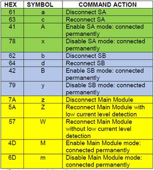
(Source: own elaboration)
2.3. SPECIFICATIONS
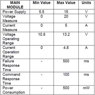
Table 2 presents a list of the principal characteristics of the Main Module of the RMU.
The RMU modules were designed to work in a scaled smart grid to measure a nominal voltage of 12 V and a maximum current of 3A. From the specifications of tables 1 and 2, the measuring ranges are the values in which the modules measures voltage and current guaranteeing a precision less than 5% of the full scale. The operation ranges are the values of voltage and current in which the modules operate normally without detecting any failure. The response time was designed with a delay of 500ms in order to detect a continuous failure and prevent a false alarm.
Table 2. Specifications of the Main Module of the RMU device
(Source: own elaboration)
Table 3 presents a list of the principal characteristics of the Secondary Module of the RMU.
Table 3. Specifications of the Secondary Module of the RMU device

(Source: own elaboration)
2.4. COMMUNICATION AND MONITORING SYSTEM
The Main Module uses an XBee module to send wireless information of the status of the grid in a data frame. The XBee modules of the RMU devices are configured in API mode [10]. The RMU devices are configured to send 2 different types of data messages every 400 ms [4].
Table 4 shows the general structure of an XBee communication frame in API mode [10].
Table 4. General structure of a XBee Rx Frame
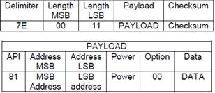
From table 4, the “7E” indicates the beginning of a frame and the “0011” indicates the length of the payload. Inside the payload, the “81” corresponds to an Rx frame, the “Address MSB” and “Address LSB” indicates the ID of the RMU that send the frame, “Power” indicates the power of the signal received, “00” is an option by default and “DATA” is a packet of bytes which contains all the information of the status of the electric grid. If the RMU detects that the voltage and current levels are correct, it sends a MONITORING DATA packet with information of voltage, current, frequency, reactive power, power factor and temperature for the monitoring system. If the RMU detects any failure, it sends a FAILURE DATA packet with information of voltage measurement and the status of the grid.
Monitoring Data
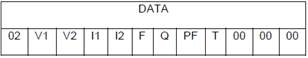
This type of message is sent only when the RMU device detects that the voltage and current levels on the grid are operating normally without any failure. In order to identify this type of message, the first byte of the data in the payload must be “02”. Table 5 shows the monitoring data frame, which is composed by 12 bytes.
Table 5. Structure of the monitoring message
(Source: own elaboration)
The first byte of the data “02” indicates that the data packet corresponds to a monitoring message. The other 11 bytes correspond to the following values:
· V1, V2: Voltage
· I1, I2: Current
· F: Frequency
· Q: Reactive power
· PF: Power factor
· T: Temperature
The last 3 bytes are always zero “00” just to increase the size of the data packet in order to have a payload of 12 bytes, which is the same size of a failure message. This was decided because by having both types of messages with the same size it would make much easier the programming of the data acquisition for the monitoring system.
An example of a monitoring message can be the following:
7E 00 11 81 31 01 A1 00 02 50 01 41 05 F8 00 FF 15 00 00 00 06
For each value in hexadecimal there is a specific constant factor that must be applied to obtain the real value of each measurement.
Failure Data
This type of message is sent only when the RMU device detects a voltage or current failure. To identify this type of message, the first byte of the data in the payload must be “03”.
Table 6 shows the monitoring data frame, which is composed by 12 bytes.
Table 6. Structure of the failure message
|
DATA |
|||||||||||
|
03 |
V1 |
V2 |
MV |
MI |
MR |
AV |
AI |
AR |
BV |
BI |
BR |
(Source: own elaboration)
The first byte of the data payload “03” indicates that the frame corresponds to a failure message. The other 11 bytes correspond to the following:
· V1, V2: Voltage value
· MV: Voltage status in the Main Module
· MI: Current status in the Main Module
· MR: Relay status in the Main Module
· AV: Voltage status in the SA Module
· AI: Current status in the SA Module
· AR: Relay status in the SA Module
· BV: Voltage status in the SB Module
· BI: Current status in the SB Module
· BR: Relay status in the SB Module
The idea of this type of message is to inform in the monitoring system the status of each module during a failure. The voltage status byte is “00” if a module detects a voltage failure, and is “01” if the voltage level is between the allowed ranges. The current status byte is “00” if a module detects a current failure, and is “01” if the current level is between the allowed ranges. The relay status byte is “01” if the relay of the module is closed and is “00” if the relay is opened.
An example of a failure message can be the following:
7E 00 11 81 31 05 B1 00 03 50 02 01 01 01 00 01 00 01 01 01 3F
3. RESULTS AND ANALYSIS
Figure 4 shows a photo of one RMU device composed by one main module (middle) and two secondary modules (left and right).

Figure 4. Photo of the RMU device (Source: own elaboration)
Multiple RMU modules were installed in a scaled smart grid in order to show the operation of an automated electric grid, by having measurement, fault detection and localization, and electric grid reconfiguration to achieve self healing. The scaled smart grid that was designed in this project is composed by three different zones, in which each zone has some special characteristics to allow a representation of a common neighbor in a city. The first zone is composed by residential, commercial and official loads, the second zone is composed by residential and commercial loads, and the third zone is composed by residential and industrial loads. With these different types of loads the idea is to show the demand response of the typical energy profiles.
The RMU modules that were installed in the scaled smart grid allow energy measurement and failure response in order to supervise the electric grid and minimize the consequences of a failure by detecting it and making self-healing.
To show the dynamics of the automated electric grid, there are two operation modes. The first one is the monitoring operation, where there are no failures in the electric grid. It is used a microcontroller with a PWM signal to change the intensity of the loads (LEDs) in order to represent a normal power demand profile during a normal day. The second operation mode is the Failure Response, where there exist some relays to generate failures by disconnecting the electric grid. In this operation mode, the idea is to show how the RMU devices detect and locate failures, and how they operate to make self-healing and isolate the damaged grid.
Monitoring System
Figure 5 shows the active power demand profile during a day in the first zone of the smart grid.
Figure 5 shows a peak of energy consumption at 1pm due to residential, commercial and official loads. A second peak of energy can be seen at 8pm due to the illumination needs at night.
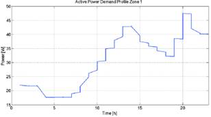
Figure 5. Active power demand profile of the first zone (Source: own elaboration)
Figure 6 shows the active power demand profile during a day in the second zone of the smart grid.

Figure 6. Active power demand profile of the second zone (Source: own elaboration)
Similarly to figure 5, figure 6 shows the energy demand profile due to residential and commercial loads, which has a first peak of energy consumption at 2pm and a second peak of energy at 9pm.
Figure 7 shows the active power demand profile during a day in the third zone of the smart grid.
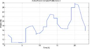
Figure 7. Active power demand profile of the third zone (Source: own elaboration)
Figure 7 shows a first peak of energy consumption in the morning at 6am due to the startup of the industrial machines, a second peak at 1pm due to residential loads, and a third peak at 8pm due to the illumination needs at night.
It’s important to notice that the third zone has a peak of energy consumption in the morning that the other two zones doesn’t have. This is because the third zone has associated some industrial loads.
Now, by having measurements of the loads consumption it can be incorporated a demand response in order to reduce the energy peaks from the different types of energy demand profiles.
Failure Response
This article presents two different examples of failure response that were made in the second zone of the smart grid using the RMU devices.
Figure 8 shows the topology of the second zone of the scaled smart grid during normal operation. In the second zone the RMU1, RMU3 and RMU4 are main modules responsible of disconnecting the main substation in case of failure in one of the transformers. The RMU2 is composed by a main module and a secondary module B which is used to make self-healing by closing a ring and allowing flow of energy between two branches. The RMU 8 is a main module that is associated to a distributed generator and is used to isolate the load node during a failure in order to operate as an isolated micro grid. The RMU 9 is a main module that is used to connect the secondary substation in case of failure in order to supply energy during a failure in the main substation.

Figure 8. Normal operation of the second zone of the scaled smart grid
(Source: own elaboration)
The RMU modules from the topology of the second zone have a circle that indicates the status of the device. If the circle is green it indicates that the module is connected and allowing flow of energy through it. If the circle is white it means that the module is opened and isolating the electric grid.
Figure 9 shows the moment in which a failure occurs in the transformer that is associated to the RMU4.
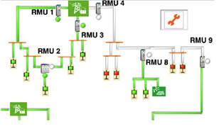
Figure 9. Failure in the transformer associated to the RMU 4.
(Source: own elaboration)
Figure 9 shows that at the moment the failure occurs, the RMU4 disconnects leaving without energy two of the load nodes. The RMU8 also disconnects making that the distributed generator supply all the energy to the associated loads.
After the failure is detected, the RMU9 connects the secondary substation (see figure 10).
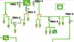
Figure 10. Failure response during a failure in the transformer associated to the RMU 4.
(Source: own elaboration)
Figure 10 shows that the RMU9 connects in order to supply energy to all the loads except the ones that are associated to the distributed generator.
After the failure is fixed, the electric grid goes back to its normal operation (see figure 8).
Figure 11 shows the active power measurement of the RMU4 and RMU9 during the failure that occurs at 10am in the transformer that is associated to the RMU 4.
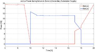
Figure 11. Failure response during a failure in the transformer of RMU 4.
(Source: own elaboration)
Figure 11 shows that when the failure occurs at 10am, the RMU4 detects a failure and disconnects the electric grid, so that’s why the active power that flows through the RMU4 is zero. Then, the RMU8 disconnects its associated loads in order to work in island mode with the distributed generator and the RMU9 connects the secondary substation (see figure 10). With this configuration, the electric grid has a backup configuration using a secondary substation in order to guarantee energy in case that a failure occurs. When the failure has been fixed (17pm), the RMU4 reconnects and then the RMU9 disconnects, so that the electric grid goes back to its normal operation.
Figure 12 shows the consequences of another failure that has been represented in the scaled smart grid by simulating a failure in the transformer that is associated in the RMU3.
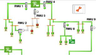
Figure 12. Failure in the transformer associated to the RMU 3.
(Source: own elaboration)
Figure 12 shows that at the moment the failure occurs, the RMU3 disconnects leaving without energy all the loads associated to the branch.
After the failure is detected, the RMU2 connects its secondary module B in order to close a ring and connect the two branches. Figure 13 shows the electric grid reconfiguration in order to overcome the failure.

Figure 13. Failure response during a failure in the transformer of RMU 3.
(Source: own elaboration)
Figure 13 shows that by closing the ring the branch associated to the RMU1 supplies the energy to the branch that has the failure.
After the failure is fixed, the electric grid goes back to its normal operation by connecting the RMU3 and then disconnecting the secondary module of the RMU2 to open the ring.
Figure 14 shows the active power measurement of the RMU1 and RMU3 during the failure that occurs at 10am in the transformer that is associated to the RMU 3.
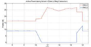
Figure 14. Failure response during a failure in the transformer of RMU 3.
(Source: own elaboration)
Figure 14 shows that when the failure occurs at 10am, the RMU3 detects a failure and disconnects the electric grid. This is why the active power that flows through the RMU3 is zero. Then, the RMU2 closes the ring so that the transformer associated to the RMU1 supplies also energy to the branch associated to the RMU3. With this configuration the electric grid has a back up configuration by closing a ring in order to guarantee energy in case that a failure occurs.
The two failures mentioned above are some examples of monitoring and failure response in an automated electric grid by using smart meters in the electric distributed network.
It was developed a SCADA system in LabView in order to control the failure response and to show a representation of a failure in the scaled smart grid. Figures 11 and 14 have a time simulation in which one hour corresponds to one second.
To evaluate the performance of the RMU device, a scaled smart grid was built to represent the operation of an automated electric grid in a neighborhood of the city by installing ten (10) RMU devices capable of measuring voltage, current, power and frequency in the different nodes of the scaled electric grid and detecting electric faults and disconnecting automatically the grid to prevent damage in the loads. Figure 15 and shows a photo of the scaled smart grid in which ten RMU devices were installed. Figure 16 shows a photo of the scaled electric grid during operation.

Figure 15. Development of the scaled smart grid using 10 RMU devices.
(Source: own elaboration)

Figure 16. Scaled smart grid during operation.
(Source: own elaboration)
4. CONCLUSIONS
The scaled automated electric grid was able to show some of the dynamics and operation modes that must have a smart grid. The RMU devices were able to control the nodes in the smart grid, by measuring the energy generated from the renewable energy sources and controlling the direction of the flow of energy depending on the demand.
Commercial RMU devices are not capable of detecting electric faults and automatically reconfigure the grid in order to make self-healing to overcome the fault by managing automatically the flow of energy in the grid. The designed RMU devices were capable of real time monitoring of the electric grid and control of nodes by disconnecting or connecting the grid in case of failures in order to make self-healing and overcome the faults. These devices can detect and locate failures in the grid, and working along with the SCADA system can improve the dynamics of the self-healing, reducing the elapsed time that takes a failure to be located and the number of users affected. The special capabilities of the RMU devices allow a reconfiguration of the electric grid during a failure in order to close electric rings and connect redundancy feeding systems, offering a better service to the users by having energy even during electric grid failures. Theses RMU devices can work as smart meters to measure some loads consumption in order to make a demand response analysis and then by taking control of the loads consumption the peaks of energy can be reduced during a normal energy demand profile. The wireless communication of the RMU devices and their modular operation, allow different configuration topologies to be automated in order to improve the energy service, increase the safety, make self-healing and guarantee redundancy feeding systems. It is important to install devices like the RMU’s in an electric distributed energy network in order to control the grid and assure a safety operation during failures and distributed generation issues.
5. ReferencES
[1] Cesar Diaz, Diego Patiño. (2015). Design and Manufacturing of a scale RMU. IEEE Conference publication.
[2] Ackermann, T., Andersson, G., & Söder, L. (2001). Distributed Generation: A Definition. Electric power system research.
[3] Chowdhury, S., & Crossley, P. (2009). Microgrids and Active Distribution Networks. IET Renewable energy Series 6.
[4] Dogan, I. Multi-tasking and real time operating systems.
[5] Donghwa, S., Younghyun, K., Yanzhi, W., & Massoud, P. (s.f.). “Battery-Supercapacitor Hybrid System for High-Rate Pulsed Load Applications".
[6] Espejo Uribe, J. S., Riaño, D., & Mejia Bonilla, D. F. (2012). Red para un sistema de generación de energía distribuido. Bogotá.
[7] Grimes, J. (2010). Using Xbee 802.15.4 in serial communication.
[8] J. D. Gabrie, G., Wagner, R., Zambenedetti, V. C., Gules, R., Lippmann, R., & Soletti, A. (2009).
[9] Protective Equipment for Distributed Generation with Integration to Smart Grids. Ampla Energía. Managing smart grids with innovative automatid ring mean units. (s.f.). EATON, Power business worldwide.
[10] Oyarce, A. (2010). Guia de usuario XBEE series 1. MCI LTDA.
[11] S. Electric, Ring Main Unit RM6 24kV. (2012).
[12] Salomón, O. (2012). La tercera revolución industrial. Mundo Eléctrico, Edición especial Smart Grids.
[13] Vandoorn, T., Zwaenepoel, B., & J. D. M., D. K. (2011). Smart microgrids and virtual power plants in a hierarchical control structure. 2nd IEEE PES International Conference and Exhibition on Innovative Smart Grid Technologies , 1 - 7.
[14] Vertanian, C. (s.f.). Microgrid standards and protocols.
[15] Yoo, B. K., Yang, S. H., & Yang, H.-S. (2011). Communication Architecture of the IEC 61850-based Micro Grid System. Journal of Electrical Engineering & Technology .
[16] Stylianos Nikitakis, Georges Argyriou. (2013). The Smarter Single Breaker RMU. A Fuse-less, Single Breaker, Auto-loop-sectionalizing RMU. 22nd international conference on electricity distribution.