1. INTRODUCTION
The airship design study in the farming environments sampling, specially of an multi-rotor, is often limited only to the prefabricated parts selection [1]. Nevertheless, when we speak about the suggested machine design, an autonomous quad-copter, it is needed to analyze and calculate, in a more detailed way, the pieces which compose this one. Then guaranteeing the viability of this new displacement method performance. Our design takes as a primary task provide, to the conventional airships kinematics, the capability of perform partial controlled on-flight inclinations. Furthermore all of this design is concentrated in the precision farming promotion, using as backgrounds, environmentally friendly designs.
2. A BRIEF CURRENT AFFAIRS REVISION
Nowadays the aircraft design has been focused on applying new or alternative construction, analysis, support and simulation modelling methodologies [2]. Three vital importance branches have been established regarding constructive and design approaches. The first, frames on the energy expense optimization. Within these it can be found the sectioning of the mathematical model and partial control actuators analysis [3]. Inclusive skills of extensive load analysis. Once the wind blasts influence, turbulences and the airships design, with combustible - battery hybrid feeding [4]. The above to satisfy design concepts which expire with remodeling and re-position methods, obtaining a minimal energetic consumption. The second branch raises that, the approach is given towards the micro modifications like pipes manufacture [5] regarding critical points detection. Also mechanical analysis as well as geometries that add rigidity to the mentioned pieces [6]. Some examples are the bee panel, Spider web, trapezoids, hexagons meeting, which allow the construction with lighter materials but also generating geometries which help to reduce the piece flexibility. The previous is frequently favorable where rigidity is needed, because other developments have implemented into the ultra-light MAVs (Micro aerial vehicles) fabrication using high flexible materials [7]. Dividing the aircraft construction methodology, in a first place the airships with simple mathematical models thanks to its rigid structures and second, the airships with complex mathematical models, which construction is based on flexible, economic and easily manufacture materials. Construction methods as micro entangling, pressure angles reinforcement, inlaid pins geometries affectations researching are some of the realized studies to materials like polymers or carbon fibers. This regarding the above mentioned characteristics [5], [6], rigidity at a lower weight. The third branch frames the approach for the alternative construction methodologies, of control and therefore of modelling. The constructive analogy with bird bodies, designing micro air devices [7] and flapping wing airships [8] are important advancements on this matter. A new design has been suggested, a ultra-light UAV (Unmanned Aerial Vehicle), designed with a 50 grams weight and with a 8 minutes maximum flight time [9]. Something that is completely meritorious to mention, since the multi-rotor airships approximate average weight ranges between 500 grams and 2 kilograms [2]. Then the association between these exposed three branches and this project lay on the innovation tendency. Not only focused in the evolution on the classical concepts, but also framed in the totally new methodologies proposals.
As is well known most of the surfaces in the nature are irregular, but also extremely fragile. In view of the above it is necessary to create an airship, in pursuance of execute precise, slow and reliable movements. Furthermore this aircraft must be powerful and stable as it must carry the sampling equipment.
June 10, 2016
3. DESIGN CASE
It is pertinent to mention that the study once autonomy current tendencies, the geometric amorphousness, the weight minimization, the UAV dimensions and costs, the new and joint control algorithms development, mistakes prediction, tasks inside work swarms planning, on-flight maintenance and data transmission, were outlined in a previous antecedents research. Those previous thematic aspects that are completely considered in this work.
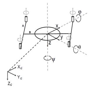
Fig. 1. Aircraft diagram, reference angles θ, φ and ψ, global coordinates system G, YG and ZG partial system X, Y and Z, A: arm type A, B: arm type B.
a. Goal approach
It is spoken about a quad-copter once the device exhibition to be analyzed and designed, whose prototyping is focused to challenge the already drones to plan new borders in the analysis and interaction with its environment. Although these small airships are every day more investigated and developed, up to today they lack of the aptitude to analyze stable surfaces at the level that would do a terrestrial robot, a surface robot or simply a human.
b. Design specifications
To archive this condition it is needed to design an airship capable to make, in stationary flights, inclinations and short displacements. In other words, this device, which can be seen on the Figure 1, must be capable to remain in {θ, φ} ≠ 0 and preserve the stationary flight with a near-zero, constant or constant accelerated speed. All this proposed from the mechanical fatigue design area.
c. Synthesis, analysis and solution selection
Inside the definitive idea selection there must be considered the following information: the airship trajectories and kinematic behavior classes, weight, dimensions, cost, speeds and accelerations, work environment, among others. From these characteristics some options can appear reaching the design specifications:
· Independent motors in two different planes rotation.
· Every type A arm independent rotation.
· Per pairs motor in only one plane rotation.
Regarding previous three options, it is possible to demonstrate that the first one of them would need to separately execute the eighth grades freedom control (two per every independent engine). Without longer reflection, it is costly and complex possibility. In the second and third place appear slightly similar options, which in a final product were provided with the same dynamics. Then, its only one difference lies in the necessary actuators population to realize the movement, one for the second option and two actuators for the third option.
The final design selection is the second option, this because it expires with the need to tilt the airship, preserving its stationary state. Using only two actuators, which perform in only one plane. Deceasing the variables number to be controlled and makes the exposition simpler.
4. DETEILED DESIGN
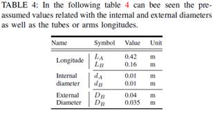
To provide with a reference point once the charges and dimensions which must support the structure, basing on a commercial airship configuration 1 the following devices in the Table 1 pre-selection 2 has done.
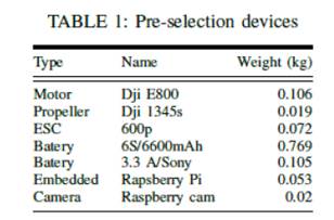
A. Material selection and statically issues:
This topic, as argued below, depends on some approaches, which was characterized by define crucial aspects into the material selection process. The most remarkable of these approaches is the necessity to manufacture a non-commercial aircraft chassis structure, forcing the maker to select an easily also light manufacture material. The second is framed on the requirement to build an aircraft sufficiently rigid, minimizing the control uncertainness also the damaging vibrations. Finally is almost a requirement develop eco-friendly device, whose construction materials must be odorless also don't lose particles, which could modify the sampling composition.
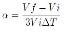
Due to the high temperatures (Around 40 °C [11] in the photosynthesis process), which could be presented in the farming process inside the Colombian tropic, has been analyzed T-expansion - T-conductivity Figure 2. The limits have been calculated by means of the volumetric thermal dilatation coefficient, where y = 3α. By α, is meant the thermal dilatation value.
![]()
Analyzing the propeller dimensions, which correspond to the pre-selected engine, an approximate length of the aircraft A and B type arms should be A: 50 cm and B: 25 cm, being this arms hollow cylinders. Then the thermal expansion factor has been calculated from (1).
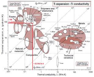
Fig. 2. T-expansion - T-conductivity comparison table from Materials selection in mechanical design by Ashby, Michael F and Cebon, D [13].
Establishing an security factor of 3 [12] 4 over the analyzed deflection (longitudinal deflection values based on the ABS material selection: in between 0.000985 m and 0.04087 m for the arm type A (the largest arm) transversal deformation) from singularity equations has been obtained a parameter equal to 83 muS/K, which give us an estimated limit in the Figure 2. As far as the thermal conductivity, the following requirement parameter, we should analyze the design initial conditions a little bit more detailed.
Is important to be careful about the manufacture method regarding the selected material. Even though not all the designed pieces would have a complex geometry, the bigger and representative ones as in this case the arms represent an exception, which need to be made-to-measure justifying the whole exhaustive executed design.
The above approach helps to rule out the majority of the materials under the thermal expansion border line (non-easily manufacturer materials). Nowadays some materials like the polymers, artificial woods, elastomer, foams, among others, can be printed by means of the 3D printing. This manufacture methodology have a lot of advantages, which in this design case can be an entirely benefit. The irregular and custom geometries printing, fast and ship prototyping and the current 3D printing adoption tendency [14], make this method a profitable option.
The ABS plastic accomplish almost all the requirements above mentioned, being a 3D user-friendly manufacture material, rigid, odorless, compact, one of the materials, which have a low thermal expansion coefficient [15]. Although there are another possible polymers, the ABS is a popular material due to it's easily acquirement also thanks to its properties and simple information sources collection. Concluding, the ABS is the selected arm material. The following table 2 summarize this 3D-polymer properties and some additional contemplations about the restrictions in efforts and deformations as operation temperature in the arms fatigue design.
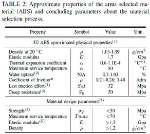
* 0.21-0.28 (chrome steel); 0.40 (aluminum)
(1) The above parameters have been obtaining from a master work made by Hyramis E.Rosales [16] also from the Handbook of Polymers by George Wypych [15].
(2) Equilibrium in water at 23 °C
(3) These limits were obtained from the Strength-Max service temperature and oung’s modulus-Density tables in Materials selection in mechanical design by Ashby, Michael F and Cebon, D [13].
(4) Limit obtained from the Local and Von-Mises efforts calculation in the fatigue arms design process.
(5) Limit obtained from the study of θ as singularity function in the static arms analysis.
(6) Value approximated obtained from [12] figure 1,”ABS-
(A) Offshore S-N Curves for Non-Tubular Details in Air” at 1.00E+06 N (Cycles) in W curve.
The above material selection was focused on the arms material, the most relevant mechanism links. Nevertheless several different parts were also considered and designed, whose related material selection, design procedures and conclusions will be discuss afterwards.
One of the most representative and sensitive elements once its weight and its size definition are the airship arms, however it is started with a simple static analysis, then identifying the critical points inside the every arm geometry. On the following Figure 3 can be seen the every arm free body diagrams.
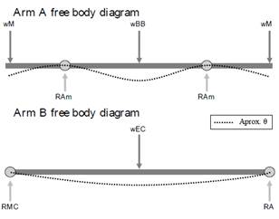
Fig. 3. Arms free body diagrams, wM: engine weight, wBB: arm B on the arm A weight, wEC: central structure on the arm B weight, RAm: dampers resultant restriction, RMC: central mechanism anchoring resultant restriction, RA: arm A resultant restriction.
This analysis is developed by means of singularity functions (q; V; M; θ; ). It is necessary to mention that this first approach is located in the moment when the airship is on rest, and the forces are simply dead charges.
Singularity equations and static approach for the arm A and B are based on:
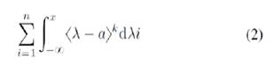
Where a represent the force location, n is the number of forces, which affect the arm. k is the grade of the power, which identifies the grade of the integral, normally q = -1; V = 0; M = 1; θ = 2; = 3. Where q is the loads influence graphic, V the cutting force diagram, M the Bending moment diagram, θ the deflection diagram and finally the Y value become the elastic curve diagram and λ frames the current function evaluation.
B. Starting aircraft fatigue design
The quad-copter performance standard is dividing into starting, stabilization, rising, displacement or fly-routine, fall, landing and finally shut-down, in that order.
Analyzing this sequence, the starting process has been found as the most demanding step. Since, on this, the aircraft must overcome its inertia. Just the motors should start with a really high angular velocity, as much the structure will be submitted by an elevated thrust. Accordingly, the starting step has been getting as design condition.
1) Arms: As a first step, it is necessary to analyze the forces, which will be applied over each arm. Initially the Dji E800 [10] engine thrust has been used as reference point, a 2,1kg/rotor @ 25V (Sea level) [17] as the maximal thrust per motor. Calculating the real thrust at a little major earth’s acceleration value (The nominal "average" value at the Earth’s surface, known as standard gravity is, by definition,[18] 9.80665 m/s2 (about 32.1740 ft./s2)), can be easily obtained a value equal to 20, 79 Newtons/rotor. Above should be multiplied by 3 as the standard ABS security factor according FATIGUE ASSESSMENT OF OFFSHORE STRUCTURES by American Bureau of Shipping [12], finally obtaining a 62.37 N/rotor thrust design value.
The overview below figure 5 the arms free-body
diagram, in the starting stage.
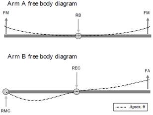
Fig. 4. Starting aircraft arms free body diagrams, FM: engine thrust, RB: Restriction on B arm, RMC: Central mechanism restriction, REC: ring central pivot restriction for B arm, FA: Force that generates arm A in arm B. The θ approximation has been exaggerated to facilitate the lecture understanding.
Following the design methodology suggested in
process of mechanical design by Ulman [19] and ”Diseño de una ménsula en voladizo para flexión variable” in Machine design by Norton [20]. The subsequent has been defined as:
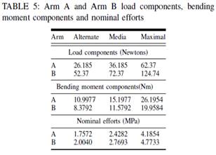
Problem: The aircraft arms will be used into a variable deflection process, this load fluctuate between 62.37 N and 10 N, it must be designed for the operation schedule seen in the Table 3.

(1) Maximal working period
Calculating the number of life cycles also multiplying the total working hours by three, being careful about the security factor of 3.8 interpolation from FATIGUE ASSESSMENTOF OFFSHORE STRUCTURES by American Bureau of Shipping [12]. A 4377.6 N (N in this case represents the number of cycles) value has been obtained as the number of aircraft arms work cycles. An estimated 180 Hz work frequency for the central mechanism further described have been calculated in base on the above parameters.
Is provided: The device will work under ambient temperature. Due to the propellers length, the arms must be dimensional proportional or longer than 13 inches. The A arm have a slot exactly in the middle to hold the T union between the A and B arm. The B arm should have a transversal hole, helping this piece to pivot around the central ring.
Assumptions: The transversal arm B hole will be suggested with a diameter of 1 cm. Being the slot of the A arm useful only to hold a piece, which due to the aircraft dynamics could be possible that it must rotate, the dimensions of this slot will be assumed with a D/d relation of 4.
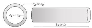
Fig. 5. L: longitude, d: internal diameter and D: external diameter assigned dimensional variables for each designed arm.
Solution: Using a simple forces summation from the figure 5 it is concluded that the forces values for A and B have the following relation equal to FA = 2FM:
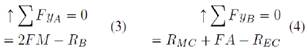
This give us the first fluctuate forces values as: FMmax = 62:37; FMmin = 10 and FAmax = 124:74; FAmin = 20.
Then calculating the alternate and middle values:
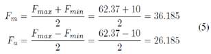
Replacing this values calculated from 5 in 3 and 4, also in the origin moments summation ΣMm, a, max for each arm, can be obtained the necessary values to calculate the nominal efforts 6. The above information can be seen summarized in the table 5. But first is calculated the inertia and transversal section centroid value (This procedure is a short inertia calculation from [20] mass properties of the basics geometric forms, which give us the values:
IA: 1; 25173e-07m4; cA: 0:02m and IB: 7; 31709e-
08m4; cB: 0:0175m.).
![]()
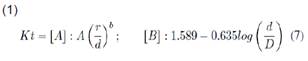
Once the D/d = A: 4; B: 3:5 and r/d: 0:1 both have been calculated r as 0.001, this from [20] Machine design by Norton, Appendix G. It is also calculated the Kt factor, the notch sensibility factor, Kf and Kfm factors (The reader can acquire further information in the figure G-5 and G-7, about the used tables in the arm A and B effort concentration factors, respectively, calculation in [20]. Machine design by Norton, appendix and chapter 4). It is also register as follows in the table 6.
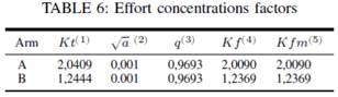
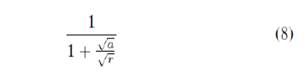
For this factors calculation the reader can analyze the following equations in some cases for arm A and arm B effort concentration factors respectively:
(2) The above Neuber parameter has been obtaining from a master work made by Hyramis E.Rosales [16] also from the Handbook of Polymers-ABS [15] by George Wypych.
(3) 
(4) ![]()
According the followed design method specifications, if Kf times the | >= max | < Sy then Kfm = Kf where >=max = |Mmax*C / I | in this case the condition meets, that is why the Kf and Kfm equality. The above is also presented when the piece is not submitted to any torque.
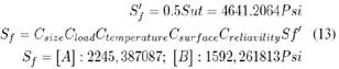
Those factors have been used to find the local efforts and these have been employed in calculate the Von-Mises efforts, which will be the same for the following reasons. First, the local efforts are calculated by means of the next equations.
![]()
Then the next expressions summarize the equality between the local and the Von-Mises efforts both expressed in the x direction. This is possible due to the y-efforts absence also because there are none torque effort, it can be easily seen as follows.
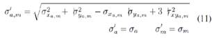
Ending the efforts calculation, a correction factor must be found. The Se value correspond to the fatigue limit resistance factor, which helps the designer to consider around five specific conveniences. Those are the work temperature, the surface manufactured, the size, the kind of load and a reliability factor. Each one from 0 to 1 multiply the Se1 value, which corresponds an uncorrected fatigue limit resistance character.
Fist is calculated the size factor, being the transversal section a circular figure, as follows:
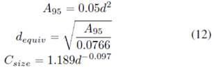
In this case the result is CsizeA = 0.5943 and CsizeB = 0.6020. Regarding the missing factors. The Cload in A is equal to 1 due to the deflection characteristic load. In the B case, allow for the possible motors dual plane rotation, this factor correspond to 0.7 for axial forces.
The rest of the factors are equal in both cases (A and B arms), Ctemperature = 1 at ambience temperature, Csurface = 1 and with a reliability of 99% (This value can be consulted in the table 4-4, Machine design by Norton [20]), Creliavility = 0:814. Finding Se1 and Se (Sf in case of polymers and other similar materials).
Two security factors per arm have been calculated verifying the design efficiency. This factors can be founded by means of the Sut factor, which corresponds to the selected material last traction effort, consigned in the table 2 as we could see in the previous calculation.
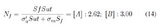
2) Central transformation mechanism: This section should begin with a short explanation about this mechanism kinematics. All the movement is powered by a central worm screw, which moves up and down a kind of nut. This nut couples a double bar connector, which joins the B arms and the central worm screw. The above approach can be faster understanding as follows in the figure 6.
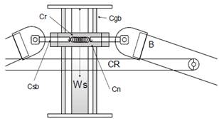
Fig. 6. Central mechanism illustration, where Ws corresponds to central worm screw, CR to central ring and B the suggested position for the B arm, Cr as the central spring, Cgb as the Central guidance bars, Csb as the Central support bars and Cn as the Central nut.
The worm screw is here allocated as a power screw. More than a methodology this design process, the design for power screws, is a complicated process. The equations are planted easily for select standardized screws. These follow equations describe the Tu or upper-torque and Td down-torque, which are the most important equations in the power screw selection.
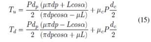
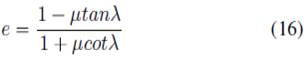
Where P is the apply axial force, dp is the diametrical pace, μ and μc the friction coefficient between the screw and the nut also the collar and the screw, respectively, L the advance, dc the ruff or collar middle diameter and finally the advance angle. Major of these parameters can be consulted and also the reader should guide himself, looking for more information about this process in the 11.2 section, chapter 11 [20], Machine design by Norton. It is important to mention also the screw efficiency formula, which help the designer to calculate the utility of his selection.
As mentioned, the screw design process is commonly a selection process. Furthermore this standardized power screws are manufactured in standardized materials too. In this occasion after an iterative process based on three different security factors (These three security factors can be consulted in a deeper way on design guides, but also in "Development of a Perforated Biodegradable Interference Screw" [21] by Patrick Hunt), the AISI 1040 (This material properties have been consulted in appendix E, Table E-9 [20], Machine design by Norton, but also corroborated in [22] "Wear properties of niobium carbide coatings performed by pack method on AISI 1040 steel” by T, Ugur Sen) carbon steel has been selected as the worm screw fabrication material. In the table 7 the reader can find the design results.
There is not any impact torsion. Due to a realized dynamical design together a vibrational impact study, which are not registered in this paper, the Jerk or acceleration differentiation are almost small to discard this character (the impact torsion).
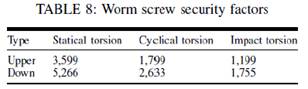
Furthermore the control system have been also designed to smooth this typical problems. Nevertheless this calculation has been considered and the three above mentioned security factors can be seen as follows, according the equation 17 and as result the values in the table 8.
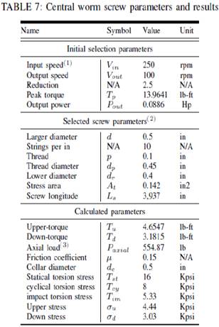
(1) This velocity is based on a low-power 50:1 Micro Metal Gearmotor HP at 360 mA.
(2) These parameters have been selected from the table 11-3, chapter 11, and Machine design [20] by Norton.
(3) This value is calculated in base on the REC maximal value, according to the forces transition in the B arm, with a value equal to 124.74 N.
The final spring, central guidance bar and central support plate's parameters and results will be consigned in the table 9.
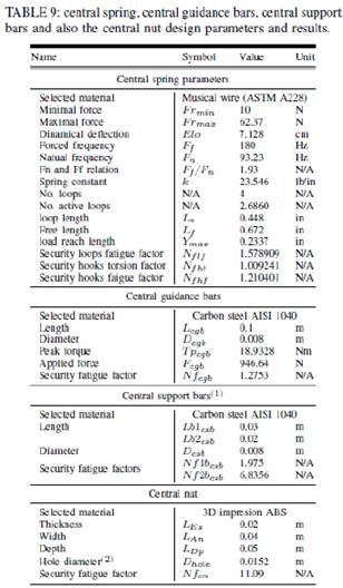
(1) These bars are divided in two pieces, which form an only U-form piece. The first piece execute the other one support and the second supports the b arm coupler.
(2) This diameter corresponds to the nut coupler. This piece must be printed, due to the strangely geometry of this central support piece.
Regarding the internal spring design, first should be calculated it's maximal and minimal elongation. Above procedure is realized by means a simple geometrical and also arithmetical calculation, it can be seen and easily understand in the figure 7, which refers to a central mechanism kinematic process summarized interpretation.
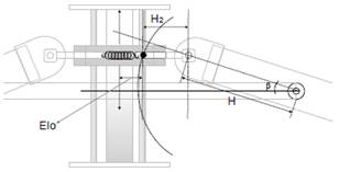
Fig. 7. Spring elongation illustration, where Elo is the spring's elongation value, H is the longitude of the b arm half longitude, H2 is a dynamical longitude and is the dynamical angle between H and the central ring.
H2 and β (Be careful about the value as sen-1(Ls/H) being Ls the total central worm screw longitude) depend on the central nut position into the mechanism, the desired calculation is the finding of Elo. This parameter can be simply approached as follows in the equation 18, which into our design have a value equal to 0:07128m or 7:12cm.
![]()
Then finalizing and making the calculation of the total device weight. It can be shortly mentioned, that this parameter is by far an important one. It is ever searched a weight reduction in the aircraft design. Regarding our case the total calculated aircraft weight is around Wt = 2:465Kg.
5. TECHNOLOGICAL APPLICATION
Albeit this design is a new proposal, its real application is not only frames in the innovation. Also this project opens a whole variety of possibilities in the intelligent robots sampling. Breaking the barriers, which limit the aircraft in its kinematic.
Where applicable the designed aircraft based on this methodology could sampling efficiently any class of irregular surface. Do not only limiting to the precision agriculture, the final goal of this approach, but also in almost whatever environment. It is important to mention that this project frames itself with the cartography, geography, precision agriculture, security, inspection, biology, zoology, ambiances where its salient sampling ease has squeezed.
6. DISCUSSION
Regarding the solution, the whole and extensive design was completely closed obtaining very good security factors in majority over 2. Considering that in a first step a 3 base security factor was suggested. It is able to stand out, that the results can be sometimes difficult to summarize and present in such a long procedure, but thanks to the design used method the whole resultant parameters have been correctly present.
This work could be taken as a designed guide, gather all the process resources and methods. As a recommendation, the reader could also refer himself to the remaining documentation of this project unregistered here. As future work, it would be precise to validate the central ring, central nut and arms design by means of a FEM analyze. A partial modification in the transversal area of the tubular arms could give them more rigidity, providing the control process.
7. ReferencEs
1] V. G. Ambrosia and T. ajkowski, “Selection of appropriate class uas/sensors to support fire monitoring: Experiences in the united states,” in Handbook of Unmanned Aerial Vehicles. Springer, 2015, pp. 2723– 2754.
[2] K. Valavanis and G. Vachtsevanos, Handbook of Unmanned Aerial Vehicles, 2015. [Online]. Available: http://library.wur.nl/WebQuery/clc/2065964
[3] H. Ryaciotaki-Boussalis and D. Guillaume, “Computational and experimental design of a fixed-wing uav,” in Handbook of Unmanned Aerial Vehicles. Springer, 2014, pp. 109–141.
[4] S. Gruber, H. Kwon, C. Hager, R. Sharma, J. oder, and D. Pack, “Uav handbook: Payload design of small uavs,” in Handbook of Unmanned Aerial Vehicles. Springer, 2014, pp. 143–163.
[5] J. Fang, Y. Gao, G. Sun, G. Zheng, and Q. Li, “Dynamic crashing behavior of new extrudable multi-cell tubes with a functionally graded thickness,” International Journal of Mechanical Sciences, vol. 103, pp. 63–73, 2015. [Online]. Available: http: //linkinghub.elsevier.com/retrieve/pii/S0020740315003203
[6] A. Khalifa, D. Weaver, and S. iada, “A single flexible tube in a rigid array as a model for fluidelastic instability in tube bundles,” Journal of Fluids and Structures, vol. 34, no. 0, pp. 14–32, 2012. [Online]. Available: http://www.sciencedirect.com/science/article/pii/S0889974612001387
[7] S. K. Phang, K. Li, B. M. Chen, and T. H. Lee, “Systematic design methodology and construction of micro aerial quadrotor vehicles,” in Handbook of Unmanned Aerial Vehicles. Springer, 2014, pp. 181–206.
[8] H. Duan and P. Li, Bio-inspired computation in unmanned aerial vehicles. Springer.
[9] S. A. Brandt, “Small uav design development and sizing,” in Handbook of Unmanned Aerial Vehicles. Springer, 2015, pp. 165–180.
[10] T. Wang, T. Zhao, H. Du, and M. Wang, “Transformable aerial vehicle,” Sep. 18 2014, uS Patent App. 14/167,679. [Online]. Available: http://www.google.com/patents/US20140263823
[11] M. E. Fernández, “Efectos del cambio climático en el rendimiento de tres cultivos mediante el uso del Modelo AquaCrop,” Tech. Rep., 2013.
[12] American Bureau of Shipping, ABS GUIDE FOR FATIGUE ASSESSMENT OF OFFSHORE STRUCTURES, 2014, vol. 2003, no. February.
[13] M. F. Ashby and D. Cebon, “Materials selection in mechanical design,” Le Journal de Physique IV, vol. 3, no. C7, pp. C7–1, 1993.
[14] T. Rayna and L. Striukova, “From rapid prototyping to home fabrication: How 3d printing is changing business model innovation,” Technological Forecasting and Social Change, vol. 102, pp. 214–224, 2016.
[15] G. Wypych, “fABSg poly(acrylonitrile-co-butadiene-co-styrene),” in Handbook of Polymers, G. Wypych, Ed. Oxford: Elsevier, 2012, pp. 3 – 10. [Online]. Available: http://www.sciencedirect.com/science/article/pii/B9781895198478500047
[16] Hyramis Edith Rosales Manrique, “METODOLOG´IA PARA EL ESTUDIO DEL COMPORTAMIENTO A FATIGA BAJO CARGA AXIAL DE MATERIALES POLÍIMÉRICOS,” Magíster en Ingeniería Mecánica, Universidad Simón Bolívar, 2006.
[17] Dji, “DJI E800 Multirotor Propulsion System,” Tech. Rep., 2015. [Online]. Available: http://www.dji.com/product/e800.
[18] T. Barry N and T. Ambler, Eds., The International System of Units (SI). Gaithersburg: National Institute of Standards and Technology, 2008.
[19] D. G. Ullman, The mechanical design process. McGraw-Hill Science/Engineering/Math, 2002.
[20] R. L. Norton, “Machine design: an integrated approach, 1996.”
[21] P. Hunt, F. N. Unterhauser, M. J. Strobel, and A. Weiler, “Development of a Perforated Biodegradable Interference Screw,” vol. 21, no. 3, pp. 258–265, 2005.
[22] U. S. T, “Wear properties of niobium carbide coatings performed by pack method on AISI 1040 steel,” vol. 483, pp. 152–157, 2005.