1. INTRODUCTION
As a growing number of users accessing new mobile technologies, telecommunications systems implement new technologies for their diffusion and improvement. Thus the Third Generation Partnership Project (3GPP) standardizes Long Term Evolution Advanced (LTE-A)[1], improving the performance objectives established in the predecessor standard.
LTE-A employs Multiplexing Orthogonal Frequency Division (OFDM)[2] as access technology, supported under Multiple Input Multiple Output systems (MIMO), and Division Duplex Frequency (FDD), establishing a performance target of 1Gbps transmission rate in the downlink[1]. The LTE-A transmitter and receiver blocks consider the cannel coding in order to detect and correct bit errors that eventually occur in the transmission. The key issue of a channel coding is to obtain from a data source 𝒄𝒌 = c0, c1, c2, …, c𝐾−1, (where 𝐾 is the number of bits to encode) an output sequence 𝒅 = 𝑑0(𝑖), 𝑑1(𝑖), 𝑑2(𝑖), …, 𝑑𝐷−1(𝑖), where 𝐷, denotes the number of encoded bits per output stream and 𝑖 indexes the encoder output stream [3]. An encoder with a rate 𝑐⁄𝑛 must contain sufficient redundancy for error correction and penalizing as little as possible the subsequent increase in bandwidth that the process generates.
European Telecommunications Standards Institute (ETSI) proposes in [3] two alternatives for the channel coding in LTE: convolutional and turbo encoders. The first one is based on shift registers and XOR operations, as is show in Fig. 1. A convolutional encoder can be completely represented by the structure (𝑰𝒔𝒓, 𝒈). The length of 𝐼𝑠𝑟 is the number of encoder inputs, the elements of this vector indicate the number of bits stored in each shift register, including the current input bits [4]. For its part, a generator polynomial 𝒈 which length represents the outputs of the encoder and the values of vector are the octal representations of connections between shift registers and sum points to each output. For instance, the encoder in Fig 1. has a structure given by (7, [133 171 165]).
A turbo encoder, for its part, is composed of two parallel convolutional encoders, one of which is affected by an interleaver, as shown in Fig. 2; this configuration is called Parallel Concatenated Convolutional Code (PCCC), in the example of the same figure the coding rate also corresponds to 1/3 being the output composed by 𝑥𝑘, 𝑧𝑘 and 𝑧𝑘 ′. The interleaver has the function of systematically permuting the order of the data to mitigate errors in bursts that can occur in the transmission [5].
A turbo encoder, for its part, is composed of two parallel convolutional encoders, one of which is affected by an interleaver, as shown in Fig. 2; this configuration is called Parallel Concatenated Convolutional Code (PCCC), in the example of the same figure the coding rate also corresponds to 1/3 being the output composed by 𝑥𝑘, 𝑧𝑘 and 𝑧𝑘′. The interleaver has the function of systematically permuting the order of the data to mitigate errors in bursts that can occur in the transmission [5].
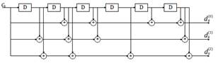
Fig 1. An example of 1/3 convolutional encoder [3].
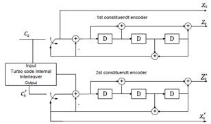
Fig 2. PPC 1/3 Turbo Encoder [3].
Previously, many studies related to channel coding have been developed, for instance in [6], [7] the coding procedure was optimized through testing several CRC rules for traditional linear block encoders. Other recent works like [8]–[12] has proposed convolutional and turbo encoders for technologies in deployment as 4G-LTE an emerging as 5G making link-level performance comparisons with well-known coding schemes or non-coding systems. In [13] the authors evaluate a turbo encoder with frame segmentation into code blocks obtaining better results than non-coding scenario in terms of Bit Error Rate (BER), the performance of proposed encoder was worsened by increasing the density of the modulation scheme. Although in this article a Simulink model is used for simulation implementation at system level, like present work, the transmission mode is SISO, AWGN channel and 16QAM as the top modulation scheme.
The study carries out in [14] is about the link-level performance analysis of novel coding schemes like Low-Density Parity Check (LDPC), and Polar Coding versus a turbo encoder, where the last one obtained the best performance in 1/3 configuration, but only evaluated with QAM modulation and Single Input – Single Output (SISO) Additive White Gaussian Noise (AWGN) channel.
It is well known that turbo encoders present higher computational complexity than block and convolutional encoders, due to most calculations, which implies a greater use of resources and therefore higher energy consumption [15].
On the other hand, in Latin American developing countries, an accelerated extension of 4G coverage is expected to increase from 60% by the end of 2016 to 80% by the end of 2017 [16]. In the case of Colombia in the third quarter of 2016, subscribers of Mobile Internet 4G surpassed 3G users [17], allowing the LTE lifecycle to be in the region's growth phase; therefore all studies that tend to optimize these systems from different approaches are relevant.
So, the present study is oriented to interpret and analyze the turbo and convolutional coding schemes performance in LTE-A downlink, representing the functional structure of transmission, channel and reception in a link-level simulation mode, considering more realistic conditions for LTE-A than previous works, such as MIMO 3x2, Rayleigh fading, and 256-QAM as the mayor modulation scheme. The objective is to determine in which cases the use of more complex encoders is necessary to keep an acceptable error rate in the transmission, and in which cases it is enough to use the convolutional encoder to employ fewer resources and reduce the energy consumption of devices.
The rest of paper is structured as follows. Section 2 is about materials and methods used to obtain the coding schemes models and perform the simulation plan employing a methodology called practitioners perspective described in [18]. In section 3 the main results of simulations are presented an analyzed focusing in performance curves of throughput and BER. Finally, in section 4, the key contributions of study are emphasized and future works are proposed.
2. MATERIALS AND METHODS
The study is addressed from a neopositivist paradigm, with a quantitative approach, an empirical analytical method and a descriptive type of research, using the approach described in [18] through the phases presented in Fig. 3.
2.1. Problem definition
The study aims to determine the performance of turbo encoding and convolutional in the downlink LTE-A considering the BER and throughput metrics. The coding is complete with block modulation LTE-A generating various Modulation and Coding Schemes (MCS) which are controlled by the packet scheduler [19].
The downlink packet scheduler take decisions from Channel Quality Indicator (CQI) to select the MCS to be used, with the development of the study it was possible to determine which encoding scheme is more appropriate for performance metrics addressed in the study, according to channel conditions.
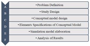
Fig. 3. Methodology used for the development of the study.
2.2. Study design
The study design considers the assumptions, models necessary to carry out the study and the tools used for the implementation and testing of the proposed model [20].
a. Assumptions
Since it is a link level simulation, the study considers the one-way communication between the eNB and receiver as well as a continuous bit stream, fading effects are modeled by Rayleigh distribution and MIMO 2x2 channel.
b. Model required for the study
The general model of downlink LTE-A, is proposed through three elements, formed by the transmitter, the channel and receiver, as shown in Fig. 4.
c. Tools.
To carry out the study, it is used MATLAB Simulink R-2015® as a simulation tool. The tool has been used in previous studies [10][9] and allows to represent the functional blocks of the transmission and reception in LTE-A.
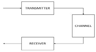
Fig. 4. General model for the LTE-A downlink.
2.3. Conceptual model design
The general model is represented by the block diagram which can be divided into three parts, as shown in Fig. 4; transmission, channel and reception respectively. Fig. 5 [10] is a model of detail in which is explained below.
In the transmission block, the Bernoulli generator is responsible for generating random bits for transmission, the source coder was implemented by a CRC generator block, which is responsible for adding information for error detection, attaching 24 bits per 1000 transmitted [11], the encoder that transforms the bit sequence with a rate of 1/3 and following the rule dictated by the generator polynomial that was configured, modulation depends on the model chosen channel, the three highest modulations of the CQI table were taken, they are 16, 64 and 256 QAM.
The channel block was modeled as a MIMO 2x2 system establishing a total of two antennas for transmission followed by a Rayleigh channel, in the second stage the AWGN channel introduces Gaussian Noise to generate uncertainty in the channel, where is possible to configure the bit Energy to Noise Density Ratio (Eb/No). Subsequently, the reception of the MIMO channel is located, where the number of antennas is established [12] [21].
At the end, in the reception block is the demodulator that depends on the type of modulation previously chosen, following this, is decoding and detection block CRC that are responsible for the error detection and correction respectively with the information received shall calculate the BER and throughput metrics [11].
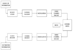
Fig. 5. General model LTE-A downlink design.
2.4. Simulation model elaboration
The construction is carried out in block diagrams, considering the mechanisms that performs LTE-A in downlink. This includes the original structure based on the blocks offered by the LTE toolbox MATLAB 2015®, thanks to this tool taken as a reference and support for this research, it manages to give way to performance analysis on each LTE-A encoder.
Schemes developed for Simulink simulation and turbo convolutional coding considered elements of the conceptual model and are shown in
Fig. 6 and Fig. 7 and explained below.
2.5. Elements specifications of conceptual model.
a. Binary Bernoulli Generator.
This block generates random binary stream using a Bernoulli distribution, transmitting zeros with probability P and ones with probability 1-P, P was setting on 0.5 to maximum uncertainty [22]. This block is configured with an output rate of 1000 bps, due to available computational resources.
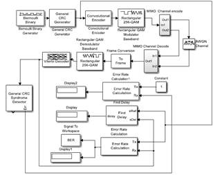
Fig. 6. LTE Convolutional coding simulation scheme.
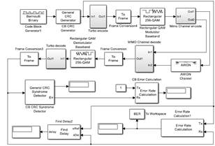
Fig. 7. LTE Turbo coding simulation scheme.
b. General CRC Generator (CRC).
CRC is block for cyclic redundancy bits generation based on a rule given by the generator polynomial for each frame of input data by adding a tail that contains relevant information for the receiver to detect the presence of errors. This block accepts an input signal of the binary vector column in the simulation model. To generate CRC tail was used as generator polynomial 𝐺(𝐷)=𝐷24+𝐷23+𝐷6+𝐷5+𝐷+1. This block produces a sequence 𝒄𝒌 whit an effective rate of 1024 bps that will be processed by the encoder.
c. Convolutional encoder.
The convolutional coding block, encodes a sequence of binary input vector 𝒄𝒌 to produce a sequence of binary output vector 𝒅 [4]. The structure chosen for convolutional encoder was (3, [7 3 5]]), which means a code rate of 1/3 and the use of 3 shift registers (including input).
d. Turbo Encoder.
The proposed coding scheme turbo shown in Fig. 8 consists of the concatenation of two convolutional encoders; to one of them, a convolutional interleaver is applied. The structure of convolutional encoders is the same as in the previous section. The turbo encoder also has a coding rate of 1/3.
e. Convolutional interleaver
The Convolutional Interleaver block permutes the symbols in the input signal. Internally, it uses a set of shift registers. The delay value of the kth shift register is (k-1) times the Register length step parameter. The number of shift registers is the value of the Rows of shift registers parameter [23]. The selected values of rows of shift registers and register length step were 6 and 2 respectively.
f. Rectangular QAM Modulator Baseband.
The Quadrature Amplitude Modulation (QAM) is a block that transforms N bits in M possible symbols according to a constellation M-QAM, the study considers 16, 64 and 256 for M value.
g. Combine Inputs using Orthogonal Space-Time Block code, (OSTBC) encoder.
Encodes input message with Code Block Orthogonal Temporary Space (OSTBC) scheme[24]. This process is necessary for generating the multiple signal streams to be delivered to the channel.
h. 3 x 2 MIMO fading channel.
Simulates the baseband of a Rayleigh’s propagation channel performing multipath fading. The diagram performing for this process is shown in Fig. 9.
i. AWGN Channel.
AWGN Channel block adds Gaussian noise to a complex input signal given by predecessor block [25]. This block is necessary to vary the channel conditions to evaluate the performance of the encoders through different values of Eb/No.
j. OSTBC Combiner.
It combines the input signal and the channel estimate signal to extract the soft information of the symbols that were encoded using an Orthogonal Space-Time Block code (OSTBC). A symbol demodulator or decoder would follow the combiner block in a MIMO communications system [26].
k. Rectangular QAM Baseband Demodulator.
The QAM baseband demodulator performs recovery of symbols adjusting the received symbols with the reference constellation.
l. Turbo decoder.
A Viterbi decoder and a deinterleaver blocks were used to recover and organize the bits that are available in the receiver, applying complementary process to turbo encoder.
m. Viterbi’s decoder.
It decodes input stream of bits from the demodulator to obtain binary output bits recovered 𝑐𝑘∗, it processes the symbols serially according to the rule set in the encoder and considering the propagation delay of bits.
n. Error Rate Calculation.
This block compares the input stream 𝑐𝑘 with the output data 𝑐𝑘∗, getting the BER of the system.
o. Performance analysis.
The throughput of each simulation is the effective bit rate transmitted to terminal per unit time, the effective rate for this simulation model is related to the efficiency of bits sent. The throughput of the link is established with the equation (1).
![]()
𝑅 is a normalized value between zero and one by a maximum reference throughput of 1024 bps that depends on sample time employed in the simulation.
The BER evaluation was performed with Bertool toolbox of MATLAB®, which is responsible for producing the performance curve for different values of Eb/No, the BER is calculated by the ratio between the erroneous bits in the receptor and the total bits transmitted for the source.
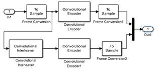
Fig. 8. Turbo encoder.
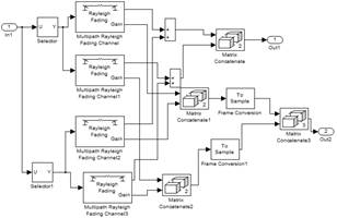
Fig 9. 3x2 MIMO fading channel.
3. RESULTS AND DISCUSSION
In this section the results of the simulations carriedout in the proposed model are presented. Table 1 shows the configuration of the parameters used to evaluate the coding schemes performance.
Table 1. Parameters established in the simulations.
|
Parameters |
Values |
|
Number of sent bits |
1000 bps |
|
CRC generator polynomial |
[1 1 zeros (1, 16) 1 1 0 0 0 1 1] |
|
Generator polynomial encoder / decoder |
poly2trellis (3, [7 3 5]) (code-rate 1/3) |
|
Modulation order |
16, 64, 256 QAM |
|
Number of bits per symbol |
4, 6, 8 |
|
Coding scheme |
Convolutional or Turbo encoder. |
|
Decoder type |
Viterbi’s decoder |
|
Energy-per-bit / spectral noise power density (Eb/No) |
0:1:35 dB |
|
Number of repetitions |
10 |
According to Fig. 10, corresponding to 16 QAM modulation BER curve, it shows that the convolutional encoder has better performance than convolutional encoder beginning from 10 dB. Figure 11 corresponds to normalized throughput, as in the previous case, the convolutional encoder has the best performance starting form 5 dB. The results show that for a relative low density modulation is suitable to use a low complexity encoder. Thus, the convolutional encoder works more efficiently than a turbo encoder for this kind of modulation. The result is valid for Internet of Things applications that demand a low throughput and require a low energy consumption such as telemetry.
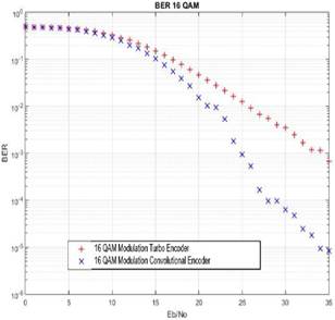
Fig. 10. 16 QAM Modulation BER Curve
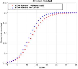
Fig. 11. 16 QAM Modulation Throughput Curve.
The Fig. 12 shows the BER behavior with 64 QAM modulator for the coding schemes selected, it is seen that the turbo encoder responds to this type of modulation with a little difference on performance starting from 6 dB. The effect of using a higher order modulator is the needing of better channel conditions, for instance, to reach a BER of 10−3 convolutional encoder in 16QAM scenario needs 25 dB of Eb/No, but in 64QAM condition require about 35 dB. However, it can be appreciated that the use of major order modulators increases the maximum system throughput.
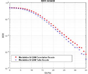
Fig. 12. 64 QAM Modulation BER Curve.
The Fig. 13 presents the normalized throughput curve where the bit rate achieved by the turbo coder is larger than the convolutional encoder in a range of 0 to 20 dB, establishing that the turbo encoder has the best performance in 64QAM modulation, the convolution encoder reach the turbo encoder with a minimal difference in the range of 20 to 35 dB, so the convolutional encoder demands better channel conditions to equate the turbo encoder performance.
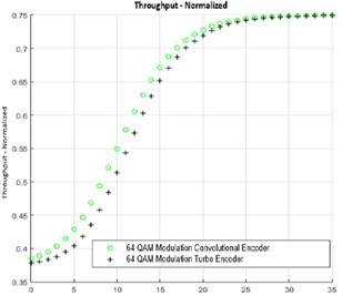
Fig. 13. 64 QAM Modulation Throughput Curve.
Fig. 14, exhibit the BER curve with 256 QAM modulation. It is observed that the turbo encoder is more efficient in a range of 26 to 35 dB, allowing the turbo coding to perform the best processing error correction, the convolutional encoder has a similar response in a range between 0 and 20 dB, so the turbo encoder is best suited for this type of modulation, considering the typical values of Eb/No of OFDMA systems, and the convolution encoder doesn´t get acceptable BER values staying suspended in an approximate value of 10-3.
Fi5 corresponds to the normalized throughput, where in Eb/No the range of 0 to 5 dB turbo encoder has a better performance, whereas the convolutional encoder gets the best response in the Eb/No range of 5 to 20 dB.
The Fig. 16 lets to compare the results of BER for overall simulation scenarios, the maximum value of BER corresponds to maximum uncertainty (BER = 0.5) at 0dB, as long as the minimum BER value is 3×10⁻⁵ obtained by convolutional encoder at 35 dB of Eb/No. In addition, by reviewing the behavior of the curves it is possible to appreciate that the convolutional encoder configuration at 16QAM is separated from the rest, tending to improve around 20dB.
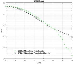
Fig. 14. 256 QAM Modulation BER Curve.
In the case of throughput it is possible to identify well-defined behaviors for each modulation order, obtaining the best performance for the configuration of 256 QAM with turbo encoder, with a throughput of 1024 bps around 30 dB of Eb/No, the maximum possible value in link-level simulation model proposed. A poor throughput performance is obtained with a minimum normalized throughput of 0.25 at 0 dB, as shown in Fig. 17.
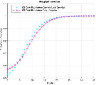
Fig. 15. 256 QAM Modulation Throughput Curve.
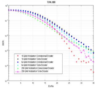
Fig. 16. BER curves for modulation and coding schemes of the study.
To complement the study, Table 2 summarizes the performance metrics at 35 dB for the scenarios carry out in the study, highlighting the best value of BER and throughput.
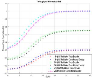
Fig. 17. Normalized throughput curves for modulation and coding schemes of study.
Due to recent previous works about convolutional and turbo coding address simplifier features (i.e. SISO, no fading channels and low order modulators like BPSK, QPSK and QAM), was possible to compare the results only with two antecedents, with 10−2 BER and 16 QAM modulation, as shown in Table 3. The present research obtained values closer to the research developed in [12] by Huawei which deals with experimental measurements of BER in devices that implement turbo encoders on a urban environment with typical values of fading on China.
Table 2. Metric values at 35dB
|
Modulator |
Encoder |
BER |
Throughput (bps) |
|
16QAM |
Convolutional |
𝟒 × 𝟏𝟎−𝟓 |
512 |
|
16 QAM |
Turbo |
7 × 10⁻⁴ |
512 |
|
64 QAM |
Convolutional |
7 × 10⁻⁴ |
768 |
|
64 QAM |
Turbo |
3.5 × 10⁻⁴ |
768 |
|
256 QAM |
Convolutional |
8.5 × 10⁻⁴ |
1024 |
|
256 QAM |
Turbo |
1.8 × 10⁻⁴ |
1024 |
Table 3. Parameters established in the simulations.
|
Articule |
Eb/No (dB) |
|
B. Zhang et al. [12] |
20 |
|
E. Migabo and T. Olwal [13] |
7 |
|
This research |
25 |
4. CONCLUSIONS
Simulation schemes performed in the present study allows to representing the LTE-A link-level behavior considering the transformation processes experienced by transmission bits and the recovery process that occurs in the receiver, focusing on evaluation of convolutional and turbo coding schemes. The models developed in the study faithfully represent the internal processes at the link level that are carried out in transmission and reception, guided by the ETSI recommendations on 4G standardization.
After evaluating the simulation scenarios was determined that for relatively low rate applications it is recommended the use of convolutional encoders that obtain a better BER performance values, this a plus point as devices with less computational expense and lower energy consumption are required. But when the bit rate is required for higher throughput applications like streaming that use 64 and 256 QAM modulations, turbo codes present the best performance. The consistent results demystify that turbo encoders always get better performance and are convenient for all applications.
For future work, it is suggested to try the model for higher values of reference throughput that requires more computational resources, adapt the simulation model for novel encoders like polar and Low Density Parity Check (LDPC), and using transmission techniques addressed by 5G mobile networks initiatives. Another proposal that emerges from this study is to characterize the pattern of energy consumption associated with the coding process that is carried out in the devices that compose the mobile network and apply classification techniques to determine which the most convenient parameters are for particular situations.
5. ReferencEs
[1] I. F. Akyildiz, D. M. Gutierrez-Estevez, and E. C. Reyes, “The evolution to 4G cellular systems: LTE-Advanced,” Phys. Commun., vol. 3, no. 4, pp. 217–244, 2010.
[2] O. G. Jorge, “Estudio de Técnicas de Codificación de Canal en Redes Celulares OFDM,” Cuadreno Red cátedras Telefónica, pp. 4–11, 2012.
[3] ETSI, “TS 136- 212 LTE, Evolved Universal Terrestrial Radio Access (E-UTRA), Multiplexing and channel coding,” 2015.
[4] MathWorks (R), “Convolutional Encoder System object,” 2015. [Online]. Available: https://www.mathworks.com/help/comm/ref/comm.convolutionalencoder-class.html. [Accessed: 10-Jun-2016].
[5] S. Haykin, Communication Systems, 4th ed. México: Wiley India Pvt. Limited, 2006.
[6] A. Thomas, K. Radhakumar, C. Attada, and B. S. Rajan, “Single Uniprior Index Coding With Min – Max Probability of Error Over Fading Channels,” vol. 66, no. 7, pp. 6050–6059, 2017.
[7] G. Durisi, E. G. Str, J. Ostman, J. Li, H. Sahlin, and G. Liva, “Low-latency Ultra-Reliable 5G Communications : Finite-Blocklength Bounds and Coding Schemes,” pp. 1–6, 2017.
[8] C. Anghel, C. Paleologu, and C. Stanciu, “Performances evaluation of CTC turbo decoder for LTE systems,” in 2015 57th International Symposium ELMAR (ELMAR), 2015, pp. 89–92.
[9] P. Gao, “Analysis and realization on turbo equalization based on 64-QAM in OFDM system,” Res. J. Appl. Sci. Eng. Technol., vol. 6, no. 4, pp. 720–728, 2013.
[10] D. Robert, W. W. Library, and L. Riche, “The performance of high-order quadrature amplitude modulation schemes for broadband wireless communication systems,” 2012.
[11] L. K. H. G, K. N. Manjunatha, M. S. Suma, C. K. Raju, P. Cyril, and P. Raj, “Design and Performance analysis of a 3GPP LTE / LTE-Advance turbo decoder using software reference models,” vol. 2, no. 7, pp. 3–6, 2011.
[12] B. Zhang et al., “A 5G Trial of Polar Code,” pp. 7–12, 2016.
[13] E. Migabo and T. Olwal, “A simulation design of LTE communication system under adaptive modulation schemes,” in 2015 International Conference on Emerging Trends in Networks and Computer Communications (ETNCC), 2015, pp. 1–6.
[14] H. Gamage, N. Rajatheva, and M. Latva-aho, “Channel Coding for Enhanced Mobile Broadband Communication in 5G Systems,” pp. 6–11, 2017.
[15] I. Yoo, B. Kim, and I. C. Park, “Reverse Rate Matching for Low-Power LTE-Advanced Turbo Decoders,” IEEE Trans. Circuits Syst. I Regul. Pap., vol. 62, no. 12, pp. 2920–2928, 2015.
[16] GSMA Intelligence, “The Mobile Economy Latin America and the Caribbean 2016,” London, 2017.
[17] MINTIC - Colombia, “Boletín trimestral de las TIC - Cifras primer trimestre 2017,” Bogota, 2017.
[18] O. Ülgen, J. J. Black, B. Johnsonbaugh, and R. Klunge, “Simulation methodology: A practitioner’s perspective,” Dearborn, MI Univ. Michigan, 2006.
[19] S. Schwarz, C. Mehlfuhrer, and M. Rupp, “Low complexity approximate maximum throughput scheduling for LTE,” in 2010 Conference Record of the Forty Fourth Asilomar Conference on Signals, Systems and Computers, 2010, pp. 1563–1569.
[20] S. Gomez Bastar, Metodologia de la investigacion. 2012.
[21] H. Taoka, S. Nagata, K. Takeda, Y. Kakishima, X. She, and K. Kusume, “MIMO and CoMP in LTE-Advanced,” NTT DOCOMO Tech. J., vol. 12, no. 2, pp. 20–28, 2010.
[22] MathWorks (R), “Bernoulli Binary Generator,” 2015. [Online]. Available: https://www.mathworks.com/help/comm/ref/bernoullibinarygenerator.html#fp12158. [Accessed: 10-Jun-2016].
[23] MathWorks (R), “Convolutional Interleaver,” 2015. [Online]. Available: https://www.mathworks.com/help/comm/ref/convolutionalinterleaver.html. [Accessed: 10-Jun-2016].
[24] MathWorks (R), “Adaptive MIMO System with OSTBC,” 2015. [Online]. Available: https://www.mathworks.com/help/comm/examples/adaptive-mimo-system-with-ostbc.html. [Accessed: 10-Jun-2015].
[25] MathWorks (R), “AWGN Channel,” 2015. [Online]. Available: https://www.mathworks.com/help/comm/ref/awgnchannel.html. [Accessed: 10-Jun-2016].
[26] MathWorks (R), “OSTBC Combiner,” 2015. [Online]. Available: https://www.mathworks.com/help/comm/ref/ostbccombiner.html. [Accessed: 10-Jun-2016].